Radio communication device receiver device and reception manner selecting method

Inactive Publication Date: 2005-07-28
PANASONIC CORP
View PDF6 Cites 33 Cited by
  • Summary
  • Abstract
  • Description
  • Claims
  • Application Information

AI Technical Summary

Benefits of technology

[0008] It is therefore an object of the present

Problems solved by technology

However, with prior art adaptive modulation schemes, if transmission power is low at the base station apparatus that transmits data, selecting the MCS that will result in high transmission rate leads to much heightened error rate, e

Method used


Image

  • Radio communication device receiver device and reception manner selecting method
  • Radio communication device receiver device and reception manner selecting method
  • Radio communication device receiver device and reception manner selecting method

Examples


embodiment 1

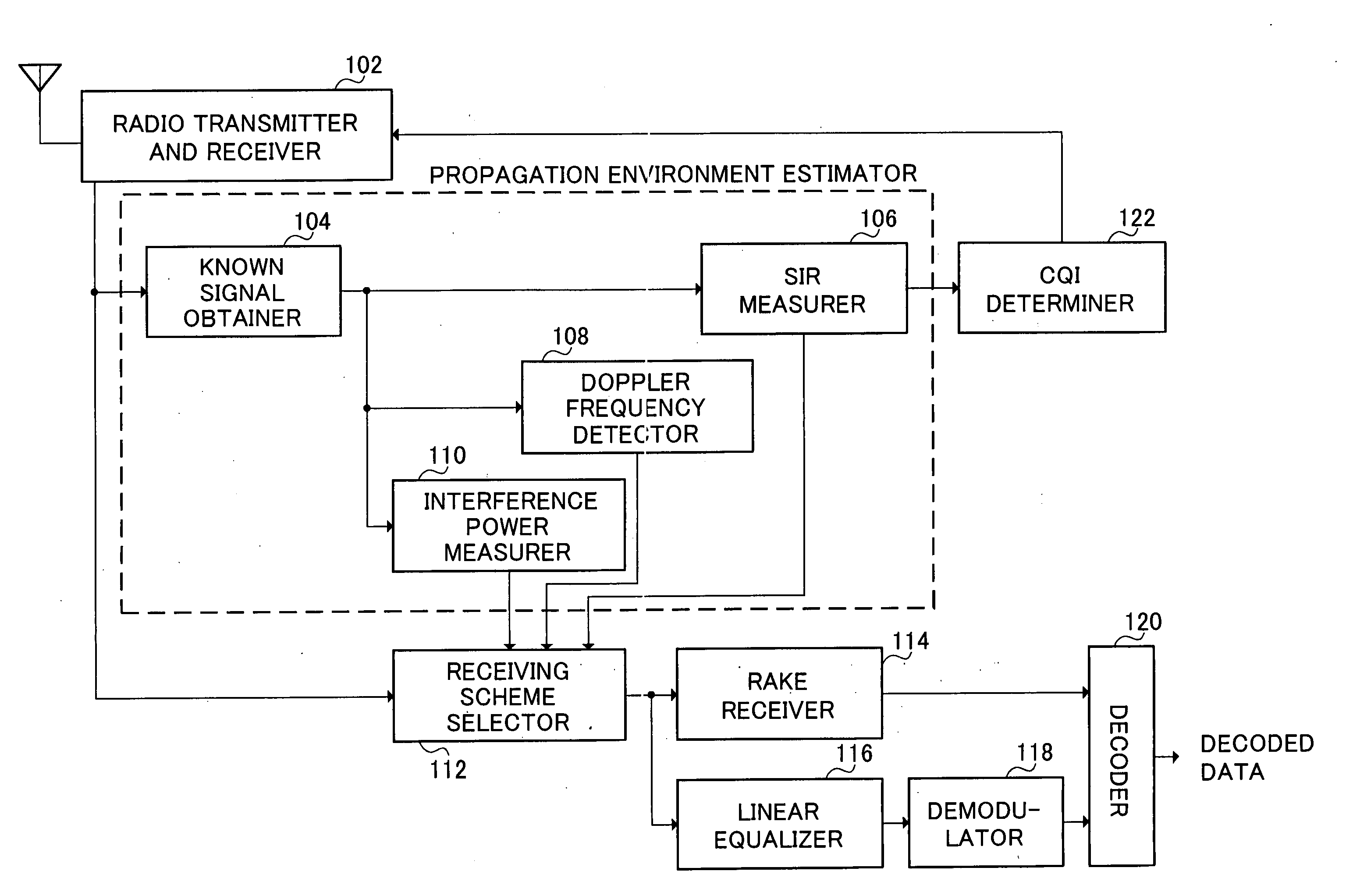
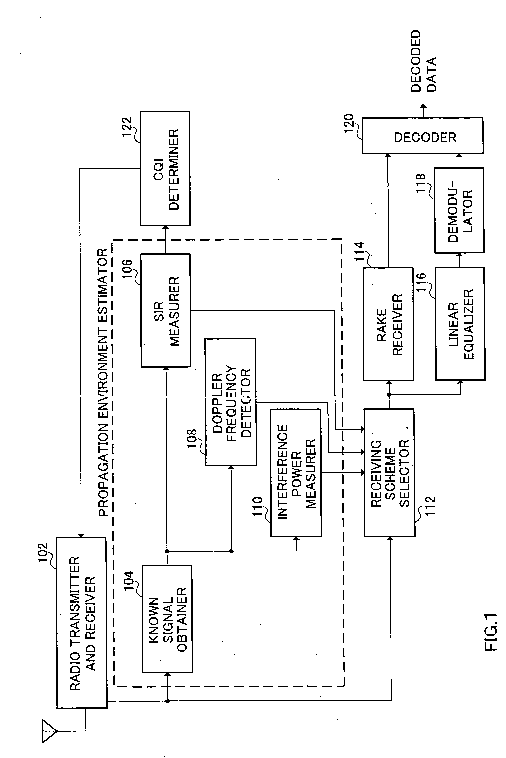
[0032]FIG. 1 is a block diagram showing the configuration of a mobile station apparatus according to Embodiment 1 of the present invention. The mobile station apparatus shown in FIG. 1 has radio transmitter and receiver 102, known signal obtainer 104, SIR measurer 106, Doppler frequency detector 108, interference power measurer 110, receiving scheme selector 112, RAKE receiver 114, linear equalizer 116, demodulator 118, decoder 120, and CQI determiner 122.

[0033] Radio transmitter and receiver 102 transmits and receives a signal through an antenna, and performs predetermined radio processing (including down-conversion, A / D conversion, D / A conversion, and up-conversion). Known signal obtainer 104 obtains a known signal from the signal received by radio transmitter and receiver 102.

[0034] SIR measurer 106 measures the SIR of the known signal. The SIR represents the ratio of signal power to interference power. According to this SIR, the CQI to be reported to the communicating base sta...

embodiment 2

[0046] A feature of Embodiment 2 of the present invention lies in having the mobile station apparatus select the receiving scheme in accordance with the propagation environment and at the same time transmit to the base station apparatus the kind of CQI's that will have high transmission rate MCS selected.

[0047]FIG. 3 is a block diagram showing the configuration of a mobile station apparatus according to this embodiment. Parts of the mobile station apparatus shown in this figure that are identical to those of the mobile station apparatus shown in FIG. 1 are assigned the same numerals without further explanations.

[0048] The mobile station apparatus shown in FIG. 3 has radio transmitter and receiver 102, known signal obtainer 104, SIR measurer 106, Doppler frequency detector 108, interference power measurer 110, receiving scheme selector 112, RAKE receiver 114, linear equalizer 116, demodulator 118, decoder 120, and CQI determiner 122a.

[0049] CQI determiner 122a determines a CQI tha...

embodiment 3

[0056] A feature of Embodiment 3 of the present invention lies in having the base station apparatus select and report to the mobile station apparatus the receiving scheme in accordance with the propagation environment.

[0057]FIG. 6 is a block diagram showing the configuration of a base station apparatus according to this embodiment. The base station apparatus shown in FIG. 6 has radio transmitter and receiver 202, Doppler frequency detector 204, CQI extractor 206, receiving scheme selector 208, report signal generator 210, MCS selector 212, adaptive encoder 214, adaptive modulator 216, and multiplexer 218.

[0058] Radio transmitter and receiver 202 transmits and receives a signal through an antenna, and performs predetermined radio processing (including down-conversion, A / D conversion, D / A conversion, and up-conversion). Doppler frequency detector 204 detects the Doppler frequency from the received signal, and measures the Doppler shift amount. The Doppler shift amount serves as an i...


PUM


Abstract

A wireless communication apparatus and a receiving scheme selection method are provided for improved overall system throughput. SIR measurer (106) measures the SIR of a known signal. Doppler frequency detector (108) detects the Doppler frequency from the received signal and measures the Doppler shift amount. The Doppler shift amount serves as an indicator of the moving speed of the mobile station apparatus. Interference power measurer (110) measures interference power from other cells. Known signal obtainer (104), SIR measurer (106), Doppler frequency detector (108), and interference power measurer (110) constitute a propagation environment estimator in this embodiment. Based on the SIR, Doppler shift amount, and interference power, receiving scheme selector (112) selects a receiving scheme of either RAKE reception or linear equalization.

Description

TECHNICAL FIELD [0001] The present invention relates to a wireless communication apparatus, a receiving apparatus, and a receiving scheme selection method. BACKGROUND ART [0002] Heretofore, in a wireless communication system, the use of adaptive modulation schemes that select, for example, MCS (Modulation and Coding Schemes, which refer to transmission rate in view of the modulation scheme and transmission rate) for improved overall system throughput in accordance with the propagation environment has been considered. [0003] Upon application of these adaptive modulation schemes of MCS selection to transmission data from the base station apparatus, first, the mobile station apparatus receives a known signal transmitted from the base station apparatus. Using the received known signal, the mobile station apparatus measures reception quality such as the SIR (Signal to Interference Ratio), and, based on this reception quality, reports a CQI (Channel Quality Indicator), which represents th...

Claims


Application Information

Patent Timeline
IPC IPC(8): H04B1/707H04B1/711H04B7/26H04L25/03H04L27/00H04W28/18H04W88/02
CPCH04B1/7097H04B1/7105H04L2025/03547H04L27/0008H04B1/7115
Inventor SHINOI, KENICHIROSUDO, HIROAKI
Owner PANASONIC CORP
Why Eureka
Try Eureka