Noise eliminator

a technology of noise elimination and filter, which is applied in the direction of gain control, transmission, radio transmission, etc., can solve the problems of deteriorating the selectivity of the desired signal in the filter, harmonic distortion, etc., and achieves the elimination of pulsed noise mixed, reduced effect, and high reliability

Inactive Publication Date: 2005-07-28
PIONEER CORP
View PDF5 Cites 4 Cited by
  • Summary
  • Abstract
  • Description
  • Claims
  • Application Information

AI Technical Summary

Benefits of technology

[0015] The present invention has been achieved in view of the foregoing conventional problems. It is thus an object of the present invention to provide a noise eliminator which re

Problems solved by technology

This can cause harmonic distortion and the like in the IF signal SIF2 due to the effect of the interruption characteristic.
This produces the problem that even if the IF signal SIF2 of which the pulsed noise is eliminated is pas

Method used


Image

  • Noise eliminator
  • Noise eliminator
  • Noise eliminator

Examples


example 1

PRACTICAL EXAMPLE 1

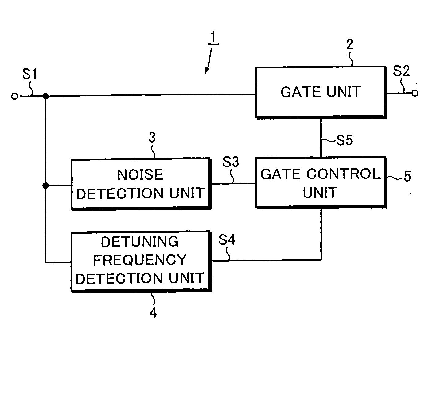
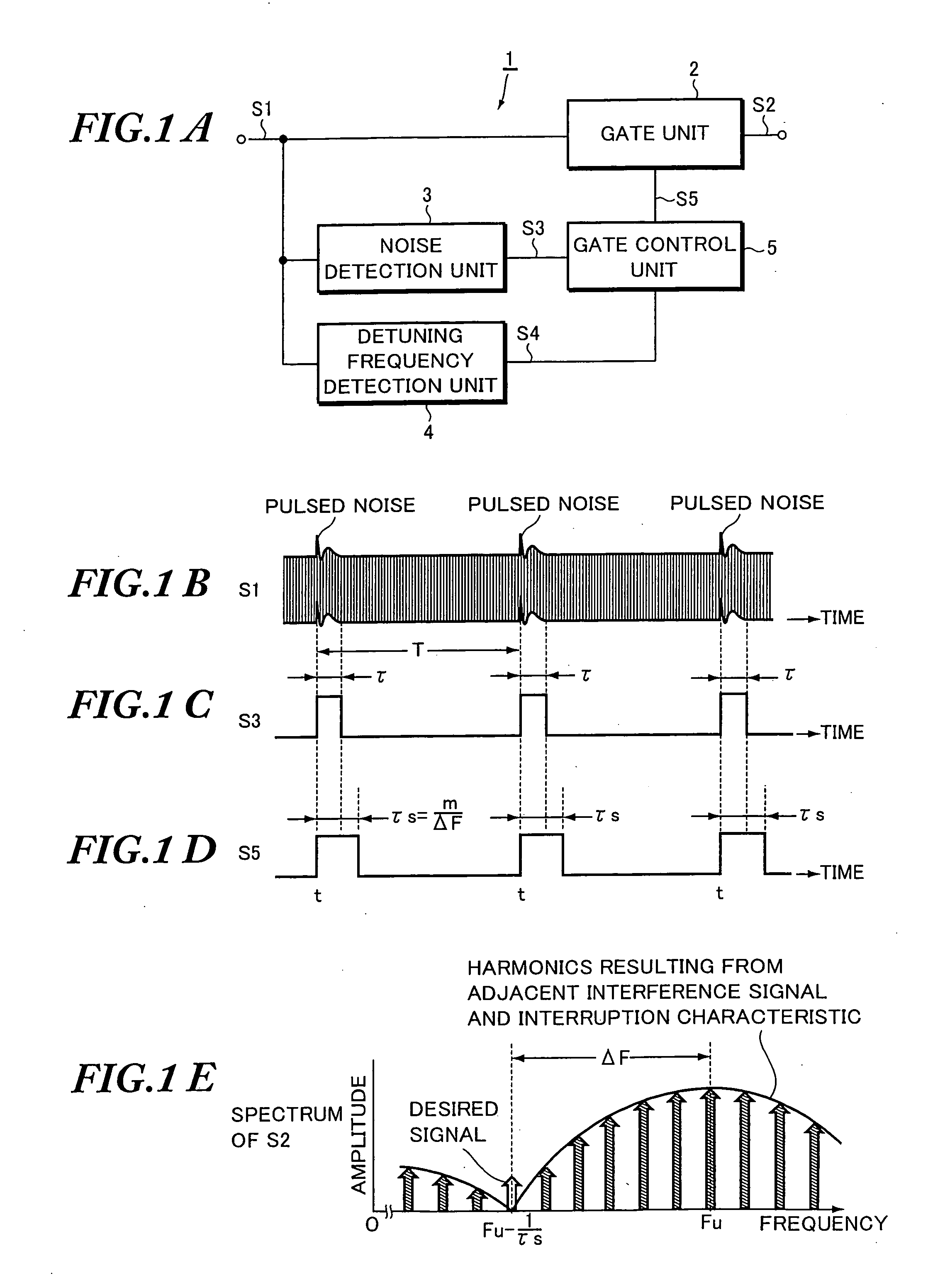
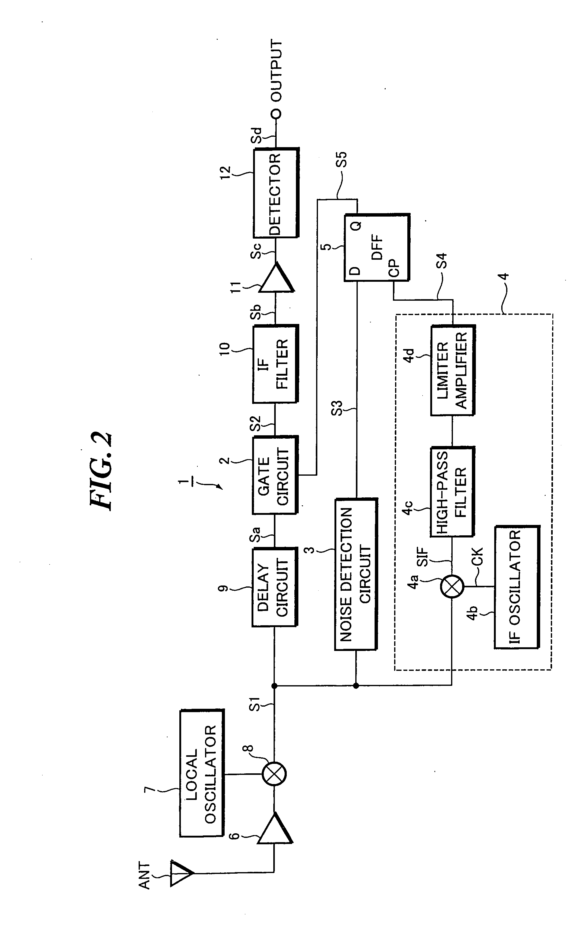
[0050] Next, a more specific practical example of the foregoing embodiment will be described with reference to FIGS. 2 to 3G. FIG. 2 is a block diagram showing the configuration of a receiver which is provided with the noise eliminator of this practical example. FIGS. 3A to 3G are waveform charts for explaining the operation of the noise eliminator. In FIG. 2, parts identical or equivalent to those of FIG. 1A are designated by the same reference numerals.

[0051] Initially, the configuration of the receiver will be overviewed with reference to FIG. 2. An RF multiplier 8 is connected to the output of an RF amplifier 6 which is connected with a reception antenna ANT. Then, the RF multiplier 8 mixes an RF signal output from the RF amplifier 6 and a local oscillation signal output from a local oscillator 7 to output a frequency-converted IF signal S1.

[0052] An IF filter 10, an IF amplifier 11, and a detector 12 are connected in series with the output of a gate circuit...

example 2

PRACTICAL EXAMPLE 2

[0083] Next, the noise eliminator 1 according to a second practical example will be described with reference to FIGS. 4 to 5C. FIG. 4 is a block diagram showing the configuration of a receiver which is provided with the noise eliminator of this practical example. FIGS. 5A to 5C are waveform charts for explaining the operation of the noise eliminator. In FIG. 4, parts identical or equivalent to those of FIGS. 1A and 2 are designated by the same reference numerals.

[0084] In FIG. 4, this noise eliminator 1 comprises a gate circuit 2, a noise detection circuit 3, a detuning frequency detection circuit 4, a DFF 5, and a delay circuit 9. The detuning frequency detection circuit 4 comprises an IF multiplier 4a, an IF oscillator 4b, a high-pass filter 4c, a limiter amplifier 4d, an AM detector 4e, a comparator 4f, and a switching circuit 4g. The AM detector 4e and the comparator 4f function as sensing means for sensing if any adjacent interference signal is superimposed ...

example 3

PRACTICAL EXAMPLE 3

[0113] Next, the noise eliminator 1 according to a third practical example will be described with reference to FIG. 6. FIG. 6 is a block diagram showing the configuration of a receiver which is provided with the noise eliminator of this practical example. In FIG. 6, parts identical or equivalent to those of FIGS. 1A, 2, and 4 are designated by the same reference numerals.

[0114] In FIG. 6, this noise eliminator 1 comprises a gate circuit 2, a noise detection circuit 3, a detuning frequency detection circuit 4, a DFF 5, and a delay circuit 9. The gate circuit 2 is interposed between a local oscillator 7 and an RF multiplier 8. The delay circuit 9 is interposed between an RF amplifier 6 and the RF multiplier 8. Moreover, the detuning frequency detection circuit 4 comprises an IF oscillator 4b, first and second multipliers 4h and 4i, a high-pass filter 4c, and a limiter amplifier 4d.

[0115] The gate circuit 2 is made of an analog switch or the like which turns on dur...


PUM


Abstract

A noise eliminator comprises: a noise detection unit for detecting the pulsed noise mixed in a reception signal, and detecting the period of occurrence of the pulsed noise; a detuning frequency detection unit for detecting an adjacent interference signal superimposed on the reception signal, and detecting a detuning frequency between the frequency of the adjacent interference signal and the frequency of a desired signal; a gate control unit for calculating a period approximated to the period of occurrence of the pulsed noise as a gate period, the gate period being an integer multiple of the period equivalent to a reciprocal of the detuning frequency; and a gate unit for interrupting the pulsed noise mixed in the reception signal during the gate period, thereby outputting a reception signal of which pulsed noise is eliminated. Thus, the noise eliminator can reduce the effect of spurious signal ascribable to an adjacent interference signal.

Description

BACKGROUND OF THE INVENTION [0001] The present invention relates to a noise eliminator for eliminating noise mixed in a signal to be processed inside a receiver. [0002] The present application claims priority from Japanese Patent Application No. 2004-7961, the disclosure of which is incorporated herein by reference. [0003] In general, it is technically important for receivers to perform signal processing based on noise-eliminated reception signals. [0004] To give a concrete example, an in-car radio receiver to be mounted on an automobile is provided with a noise eliminator for eliminating pulsed noise such as ignition noise mixed in an intermediate frequency signal (IF signal), so that signal processing is performed based on the noise-reduced IF signal (see Japanese Patent Application Laid-Open No. Hei 6-112853; hereinafter, referred to as patent document). [0005]FIG. 7 is a block diagram showing the schematic configuration of a receiver to which the noise eliminator shown in FIG. 1...

Claims


Application Information

Patent Timeline
IPC IPC(8): H03G3/34H04B1/10
CPCH03G3/345
Inventor AKIYAMA, KICHIRO
Owner PIONEER CORP
Why Eureka
Try Eureka