Introducer sheath with retainer

a technology of introducer sheath and retainer, which is applied in the field of introducer sheaths with retainers, can solve the problems of greater frictional contact with the inside wall greater likelihood of dislocation, and dislocation of the sheath, so as to overcome the disadvantages and deficiencies, and restrict the sliding movement of the introducer sheath

Inactive Publication Date: 2005-07-28
REX MEDICAL LP
View PDF32 Cites 117 Cited by
  • Summary
  • Abstract
  • Description
  • Claims
  • Application Information

AI Technical Summary

Benefits of technology

[0012] The present invention overcomes the disadvantages and deficiencies of the prior introducer sheaths by advantageously providing an introducer sheath having a retainer that is selectively extendable with respect to the sheath, thereby functioning to retain the sheath within the vessel. Extending the retainer radially from the sheath creates an enlarged diameter region greater than the diameter of the incision into the vessel to prevent withdrawal of the sheath through the incision, and in smaller vessels, enabling the retainer to frictionally engage the vessel wall to restrict sliding movement of the sheath.

Problems solved by technology

This relatively tight fit oftentimes results in excessive frictional engagement with the inside wall of the sheath, causing dislodgement of the sheath during instrument withdrawal through the passageway in the sheath.
However, after the balloon is inflated inside the vessel and then deflated for withdrawal, it is not as tightly wrapped as initial insertion.
Thus, when the balloon catheter is withdrawn through the introducer sheath, there is a greater frictional contact with the inside wall of the sheath and therefore a greater likelihood of dislodgement.
Dislodgement of the sheath creates numerous problems.
If the position of the sheath is altered by removal of an instrument, when the next instrument is inserted, it will not properly be positioned at the surgical site.
Thus the surgeon must undertake the time consuming task of repositioning the sheath and instrument within the vessel.
The problems with dislodgement become more acute if withdrawal of the instrument actually pulls the introducer sheath out of the vessel wall incision altogether.
Such undesirable removal of the introducer sheath can cause loss of blood, air aspiration which can result in air embolisms possibly causing stroke, and an increased risk of infection and morbidity.
Additionally, since the surgeon needs to reintroduce the introducer sheath into the vessel, the surgeon may be unable to locate the exact prior incision site, thereby having to enlarge the incision site or create a second incision, thereby causing additional blood loss and increasing the difficulty of closing the vessel incision(s) at the end of the procedure.
Vessel fatigue can also result because re-introduction of the sheath requires insertion of a needle and dilator through the vessel wall.
Another disadvantage of complete dislodgement of the sheath is the additional time required to re-introduce the sheath.
This time loss can be especially significant if re-introduction is required at a critical time of the procedure.
That is, if the sheath is fully withdrawn from the vessel, access to the vessel will be temporarily denied, thereby interrupting the surgical procedure which can mean appropriate instrumentation, perhaps even life-saving instrumentation, cannot be inserted to the surgical site.
However, over-insertion of the introducer sheath can adversely affect surgical access as the surgical site can be blocked by the sheath, especially if the site is adjacent the incision.

Method used


Image

  • Introducer sheath with retainer
  • Introducer sheath with retainer
  • Introducer sheath with retainer

Examples


first embodiment

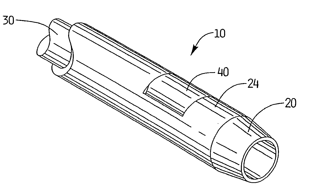
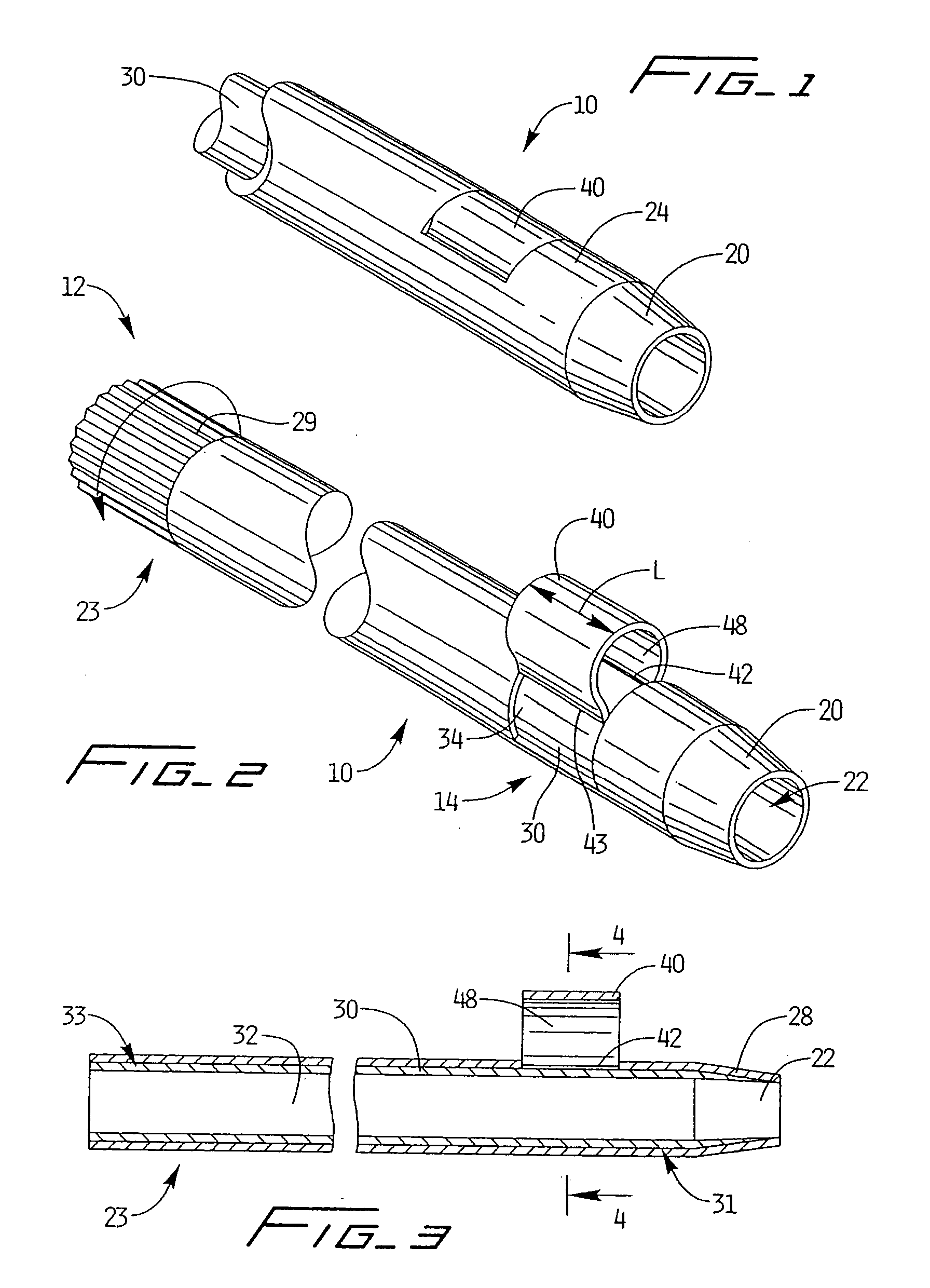
[0058] Referring now in detail to the drawings where like reference numerals identify similar or like components throughout the several views, FIGS. 1-5 illustrate the introducer sheath of the present invention, designated generally by reference numeral 10.

[0059] The introducer sheath 10 has a proximal portion 12, a distal portion 14, an outer tubular member 20 and an inner tubular member 30 disposed concentrically within the outer tubular member 20. A retainer 40, in the form of a curved or U-shaped flap, extends from outer tube 20 and is positioned proximally of the distalmost tip. Retainer 40 is movable from a retracted position where it is substantially flush with the outer surface 24 of outer tube 20 as shown in FIG. 1, to an extended (blocking) position where it extends radially outwardly from the outer tube 20 as shown in FIG. 2. This radial movement increases the overall circumference or diameter of the outer tube 20, thereby causing the sheath 10 to engage the vessel wall o...

third embodiment

[0074]FIGS. 16-19 illustrate the locking sheath of the present invention, designated generally by reference numeral 150. Locking sheath 150 is similar to the foregoing locking sheaths in that it has a retainer 160 in the form of a U-shaped flap that is movable between a retracted substantially flush position to a radially extended position with respect to the outer tube 162. Locking sheath 150 differs in the locking structure for the retainer 160 and some of the assembly components.

[0075] More specifically, and with reference to FIG. 17, inner tube 170 extends integrally from housing 172. Side port 179 for mounting conventional tubing as described above (not shown) is shown angled at about 45-degrees to reduce mechanical hemolysis. Inner tube 170 is preferably composed of a dark material, achieved for example by adding carbon black or other particles or by inks or pigments, to absorb laser wavelengths to create heat to laser weld the retainer 160 to the inner tube 170 (see FIG. 18)....


PUM


Abstract

A surgical introducer sheath comprising a first member having a first longitudinally extending lumen dimensioned to receive a surgical instrument therethrough, a second member having a second longitudinally extending lumen dimensioned to receive the first member, and a retainer adjacent a distal portion of the second member movable from a first retracted position to a second extended position to limit proximal movement of the introducer sheath. Rotational movement of the second member in a first direction moves the retainer to the extended position and rotational movement of the second member in a second direction moves the retainer to a retracted position.

Description

[0001] This application claims priority from U.S. application Ser. No. 09 / 996,437, filed Nov. 28, 2001 which claims priority from provisional application Ser. No. 60 / 251,567, filed Dec. 6, 2000. The entire contents of both applications are incorporated herein by reference.BACKGROUND [0002] 1. Technical Field [0003] This application relates to an introducer sheath and more particularly to a vascular introducer sheath having a retainer to prevent dislodgement during use. [0004] 2. Background of Related Art [0005] An introducer sheath is commonly used in vascular surgery as an access port for surgical instruments. The introducer sheath has a central passageway to accommodate such instrumentation and is inserted through a skin incision and into the vessel wall, such as the renal or femoral artery or vein, so the instruments can access the interior of the vessel. The introducer sheath can also be inserted into dialysis grafts to provide access to the graft. The introducer sheaths have pe...

Claims


Application Information

Patent Timeline
Patent Type & Authority Applications(United States)
IPC IPC(8): A61M25/04A61M25/06A61M39/04A61M39/06
CPCA61M25/04A61M25/0662A61M39/045A61M39/0606A61M2039/0686A61M2039/062A61M2039/0633A61M2039/064A61M2039/0653A61M2025/0681A61M29/00
Inventor MCGUCKIN, JAMES F. JR.TASHJIAN, PAUL
Owner REX MEDICAL LP
Why Eureka
Try Eureka