
Implantable medical device

Inactive Publication Date: 2005-07-28
BIOPHAN TECH
View PDF4 Cites 37 Cited by
  • Summary
  • Abstract
  • Description
  • Claims
  • Application Information

AI Technical Summary

Problems solved by technology

Furthermore, the stent Faraday Cage likely impedes the escape of whatever signal is generated in the lumen.
The stent's high magnetic susceptibility, however, perturbs the magnetic field in the vicinity of the implant.
This alters the resonance condition of protons in the vicinity, thus leading to intravoxel dephasing with an attendant loss of signal.
The net result with current metallic stents, most of which are stainless steel, is a signal void in the MRI images.
Unfortunately, most metal stents, particularly of stainless steel, obliterate MRI images of the anatomy in their vicinity and obscure the stent lumen in the image.
This solution is limited by the need for stents to have adequate radial strength and scaffolding.”
. . radial strength and scaffolding . . . . ” These “discontinuities” also present their own imaging problems when the stent is subjected to the fields normally present in magnetic resonance imaging.

Method used


Image

  • Implantable medical device
  • Implantable medical device
  • Implantable medical device

Examples


Embodiment Construction

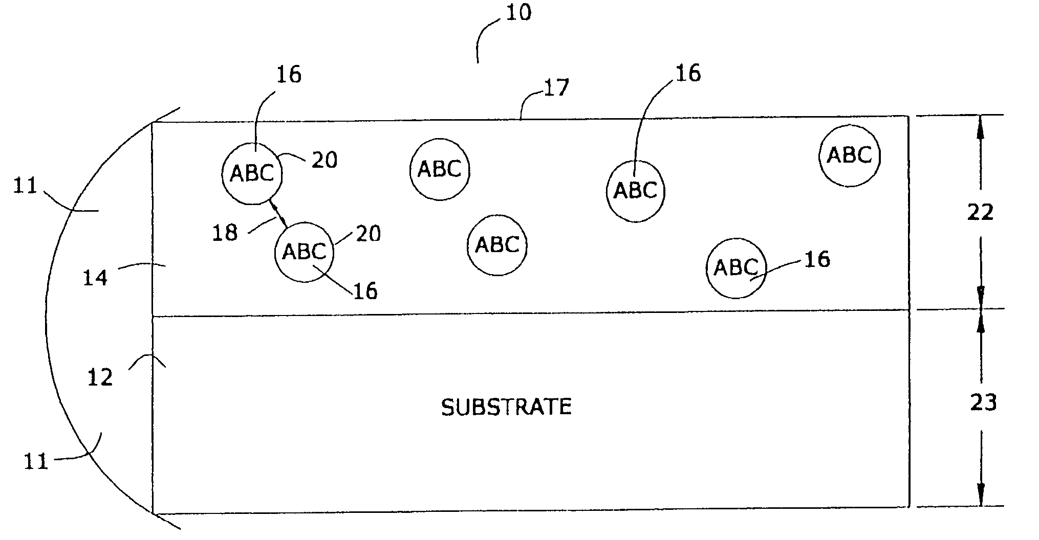
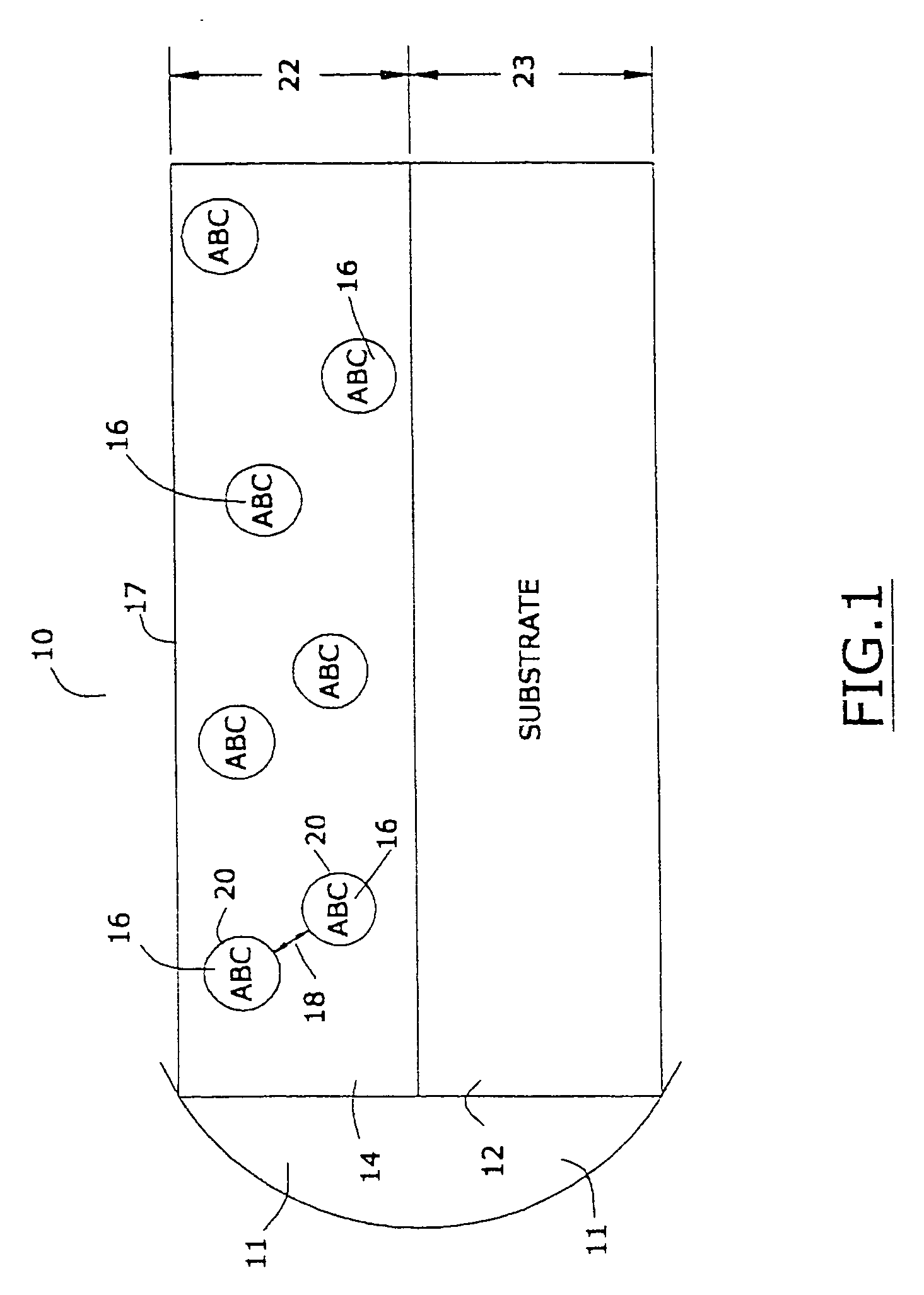
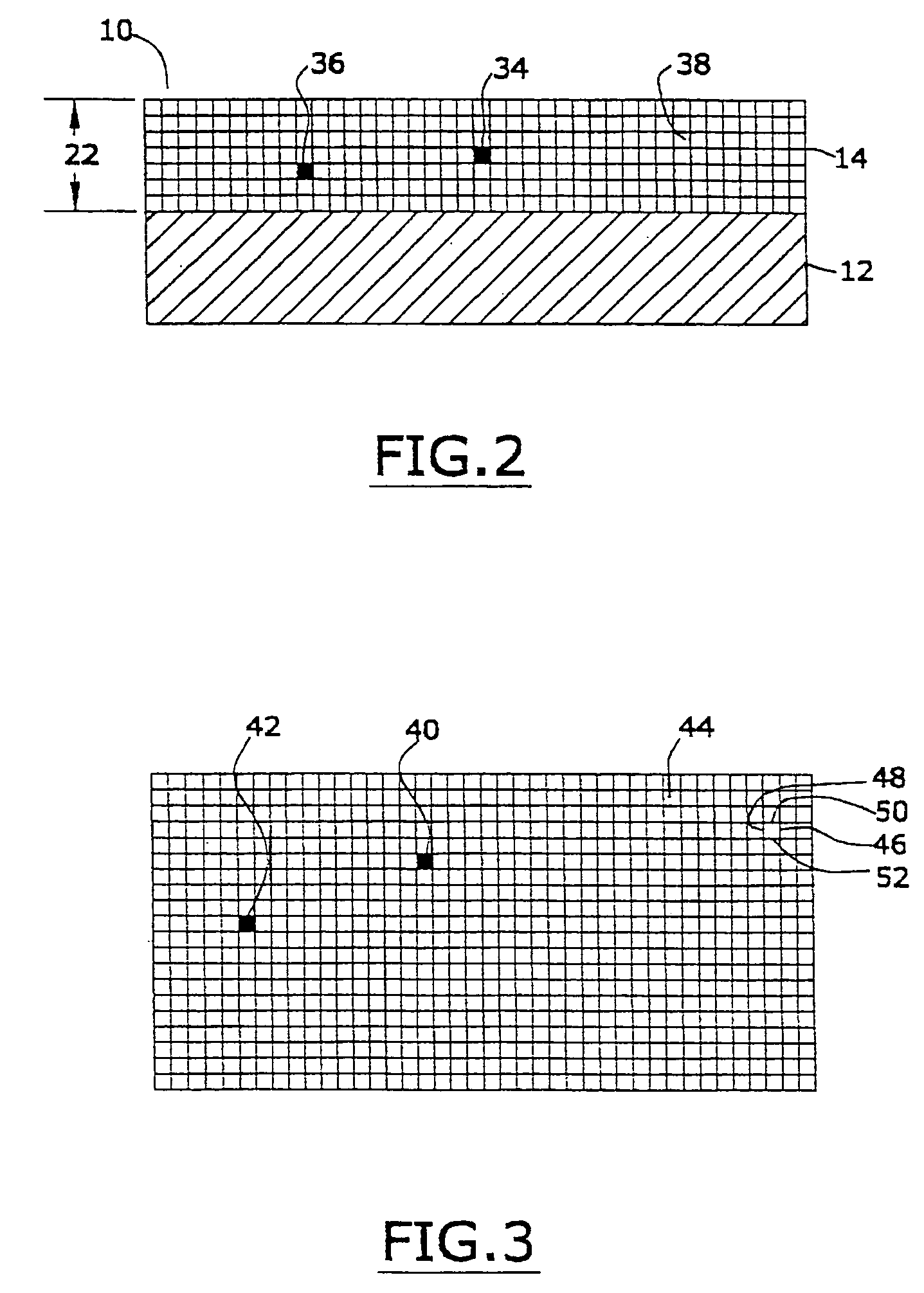
[0033] In the first portion of this specification, some the properties of applicants' preferred nanomagnetic material are described. In the second portion of this specification, applicants will describe a preferred process for preparing such nanomagnetic material. In the last part of this specification, applicants will describe certain preferred devices that comprise the preferred nanomagnetic material.

The Magnetic Permeability of the Nanomagnetic Material

[0034] Applicants have described, in several of their prior United States patents, a preferred nanomagnetic material. Reference may be had, e.g., to U.S. Pat. No. 6,506,972 (magnetically shielded conductor), U.S. Pat. No. 6,673,999 (magnetically shielded assembly), U.S. Pat. No. 6,700,472 (magnetic thin film inductors), U.S. Pat. No. 6,713,671 (magnetically shielded assembly), and U.S. Pat. No. 6,765,144 (magnetic resonance imaging coated assembly). The entire disclosure of each of these United States patents, especially as it r...


PUM


Abstract

A metallic stent that, when it is contacted with an input alternating current electromagnetic field and a static magnetic field that contacts biological matter located within the stent, an output signal is produced that that has a fixed phase relationship with the input signal and that has a magnitude that is at least about 0.01 times as great as the magnitude of the input signal.

Description

CROSS-REFERENCE TO RELATED PATENT APPLICATIONS [0001] This application is a continuation-in-part of applicant's U.S. patent application Ser. No. 10 / 923,579, filed on Aug. 20, 2004, which in turn was a continuation-in-part of each of applicants' copending patent application Ser. No. 10 / 914,691 (filed on Aug. 8, 2004), Ser. No. 10 / 887,521 (filed on Jul. 7, 2004), Ser. No. 10,867,517 (filed on Jun. 14, 2004), Ser. No. 10 / 810,916 (filed on Mar. 26, 2004), Ser. No. 10 / 808,618 (filed on Mar. 24, 2004), Ser. No. 10 / 786,198 (filed on Feb. 25, 2004), Ser. No. 10 / 780,045 (filed on Feb. 17, 2004), Ser. No. 10 / 747,472 (filed on Dec. 29, 2003), Ser. No. 10 / 744,543 (fled on Dec. 22, 2003), Ser. No. 10 / 442,420 (filed on May 21, 2003), and Ser. No. 10 / 409,505 (flied on Apr. 8, 2003). The entire disclosure of each of these patent applications is hereby incorporated by reference into this specification.FIELD OF THE INVENTION [0002] An implantable medical device that, when imaged by magnetic resonance...

Claims


Application Information

Patent Timeline
IPC IPC(8): A61F2/82A61L31/14A61L31/16H02J7/00
CPCA61F2/82A61L31/14A61L31/16B82Y25/00B82Y15/00B82Y20/00A61L2300/00
Inventor WANG, XINGWUGREENWALD, HOWARD J.
Owner BIOPHAN TECH
Learn More