
Hybrid hydrogen storage container and method of storing hydrogen in container

a hydrogen storage container and hybrid technology, applied in the direction of rigid containers, transportation and packaging, mechanical equipment, etc., can solve the problems of not being able to obtain a container capable of storing 5 kg hydrogen, not being able to meet the needs of fuel cell powered vehicles, and being difficult to mount on vehicles. , to prevent the active hydrogen absorbing material powder from forming, the effect of preventing the powder from absorbing active hydrogen

Inactive Publication Date: 2005-08-04
NAT INST OF ADVANCED IND SCI & TECH +1
View PDF5 Cites 12 Cited by
  • Summary
  • Abstract
  • Description
  • Claims
  • Application Information

AI Technical Summary

Benefits of technology

[0021] It is possible to provide a hydrogen storage container capable of charging 5 kg of hydrogen into a container having an external volume of less than 200 L and a total weight of less than 200 kg, by using a hydrogen absorbing material having a certain hydrogen absorbing capacity at a pressure of 30 MPa or higher (maximum hydrogen absorption amount per unit volume of the hydrogen absorbing material, αm≧100 kg / m3), and adjusting the volume fraction of the hydrogen absorbing material with respect to the internal volume of the container and the pressure value during charging of hydrogen into the container.
[0022] By causing hydrogen absorbing material powder in the container to be held on a carrier, it is enabled not only to prevent the active hydrogen absorbing material powder from being dispersed widely to the external system in case of an emergency, but also to decrease the uneven distribution of the powder within the container.
[0041] When the amount of the hydrogen absorbing material is increased, the volume efficiency of hydrogen storage is improved, whereas the weight efficiency is decreased. In contrast, when the amount of the hydrogen absorbing material is decreased, the weight efficiency of hydrogen storage is improved whereas the volume efficiency is decreased. Therefore, it is necessary to set an optimal volume fraction of the hydrogen absorbing material with respect to the internal volume of the container.
[0046] As stated above, it becomes possible by using the present invention to provide a hybrid-type hydrogen storage container that is easy to mount on a vehicle in terms of the space and weight, and is still capable of functioning stably and safely during use. More specifically, it is possible to provide a hybrid-type hydrogen storage container that is capable of charging 5 kg of hydrogen into the container with an external volume of less than 200 L and a total weight of less than 200 kg, and is also capable of preventing the active hydrogen absorbing material powder from being dispersed widely to the external system in case of an emergency.

Problems solved by technology

However, the high-pressure hydrogen storage container as mentioned in (1) provides only a small hydrogen storage amount per volume of the container, requiring a larger volume of the container to store a required amount of hydrogen, and thus is not suitable for use in fuel cell powered vehicles or the like.
However, since a hydrogen storage amount per weight of the container is small, a problem is posed that the weight of the container becomes remarkably heavy.
In other words, with the technology currently available, a high-pressure hydrogen storage container is required to have a weight of at least 100 kg and a volume of at least 200 L for satisfying the requirement of storing 5 kg hydrogen, and a hydrogen absorbing alloy container is required to have a weight of at least 200 kg and a volume of at least 100 L. Thus, it is not possible to obtain a container that is capable of storing 5 kg hydrogen and yet has an external volume of less than 200 L and a total weight of less than 200 kg.
Further, regarding the liquid hydrogen storage container mentioned in (3) above, the heat insulation efficiency of the container is required to be high, and there is also a problem that hydrogen tends to be vaporized by heat entering from the outside during the storage and the vaporized hydrogen gas must be discharged out of the container.
Therefore, according to the conventional technology, it is difficult to obtain a light-weight and small-sized hydrogen storage container that is capable of storing hydrogen for a long period of time.
Neither the high-pressure hydrogen storage container nor hydrogen absorbing alloy container currently available can be mounted easily on a vehicle for the reasons of space and weight.
Also, with the liquid hydrogen storage container currently available, it is difficult to dispose of hydrogen vaporized by heat entering during the halt of a vehicle, and hence it is difficult to employ such a container as a hydrogen container for fuel cell powered vehicles.
However, at a pressure level of less than 30 MPa, it is almost impossible, by using a hydrogen absorbing alloy with αm=100 kg / m3, to obtain a container satisfying the requirements for a hydrogen storage container used for fuel cell powered vehicles, namely a container that has an external volume of less than 200 L and a total weight of less than 200 kg and is still capable of supplying 5 kg hydrogen.
Sho 61-252997 is applied to a fuel cell powered vehicle, a problem is posed that the hydrogen absorbing material, that is not fixed, will be exposed to vibration during the running of the vehicle and will be unevenly distributed in the container.
However, when such a high pressure is used, there is posed a problem that, in case of an emergency, such as a collision of the vehicle, active hydrogen absorbing material powder will be dispersed widely to the external system to cause dust explosion, and the risk of inducing a secondary disaster such as a fire will be increased.

Method used


Image

  • Hybrid hydrogen storage container and method of storing hydrogen in container
  • Hybrid hydrogen storage container and method of storing hydrogen in container

Examples


Embodiment Construction

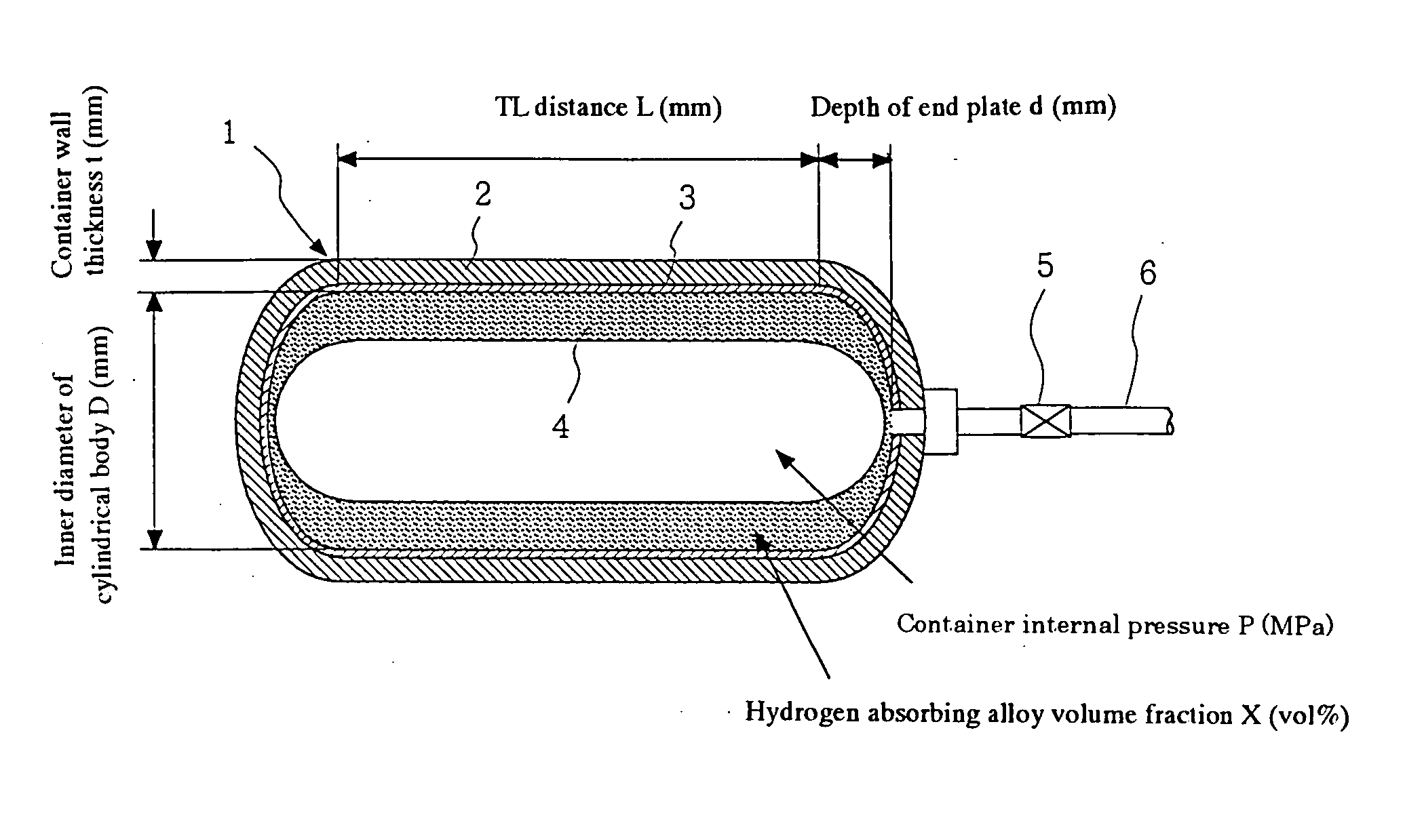
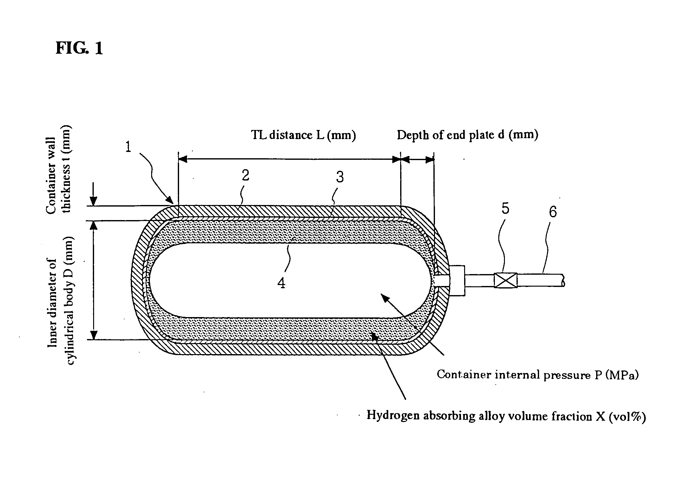
[0048] An embodiment of the present invention will now be described with reference to the drawing. FIG. 1 is a conceptual drawing showing, in cross section, an example of a hybrid-type hydrogen storage container of the present invention. In the drawing, the reference numeral 1 denotes a pressure container that is shown in a double-layer structure consisting of a reinforcing layer 2 and a liner layer 3. A pipe 6 provided with a valve 5 is attached to the pressure container 1. A hydrogen absorbing material portion (carrier+hydrogen absorbing material) 4 representing a hydrogen absorbing material held by a carrier is contained inside the pressure container 1 and is fixed so as not to be moved by vibration during transportation or the like. Hydrogen is charged into the inside of the pressure container 1 at a charging pressure of 30 MPa or higher.

[0049] The pressure container 1 naturally needs to have adequate strength and pressure resistance, and hence should be constructed with a spec...


PUM


Abstract

A pressure container 1 composed of a reinforcing layer 2 and a liner layer 3, with a hydrogen charging pressure of 30 MPa or higher; and a hydrogen absorbing material and a carrier for holding said hydrogen absorbing material (hydrogen absorbing material portion 4) contained in the pressure container 1 are included, and a volume fraction X of the hydrogen absorbing material with αm≧100 kg / m3 with respect to an internal volume of the pressure container 1 is 5(%)≦X≦20(%), where am denotes a maximum hydrogen absorption amount per unit volume of the hydrogen absorbing material (kg / m3); X=100 ·Vm / Vi (%); Vi is an internal volume of the pressure container (L); and Vm is a volume of the hydrogen absorbing material in the pressure container (L).

Description

TECHNICAL FIELD [0001] The present invention relates to a hybrid-type hydrogen storage container to be used for supplying hydrogen to fuel cell powered vehicles in transportation equipment, fuel cells for decentralized power generation, and the like, and to a method of storing hydrogen in such a container. BACKGROUND ART [0002] A fuel cell, which generates power by reacting hydrogen with oxygen in air, is required to be supplied with hydrogen as an energy source. The supply of hydrogen to fuel cell equipment can be implemented by several methods as follows: [0003] (a) supplying hydrogen by reforming town gas, LPG, or the like into hydrogen in the vicinity of consumption equipment; [0004] (b) supplying hydrogen directly through a pipeline; and [0005] (c) supplying hydrogen by installing a hydrogen storage container in the vicinity of consumption equipment. In the mean time, various hydrogen supplying methods are studied so as to suit a scale of equipment, intended use, or the like. I...

Claims


Application Information

Patent Timeline
Patent Type & Authority Applications(United States)
IPC IPC(8): F17C1/04F17C11/00
CPCY02E60/321F17C11/005Y02E60/32
Inventor YOKOTA, TOMOYUKIHAMADA, KENJIROTSURUTA, HIDEKAZUKURIYAMA, NOBUHIROTAKESHITA, HIROYUKITAKEICHI, NOBUHIKOTAKANO, TOSHIO
Owner NAT INST OF ADVANCED IND SCI & TECH
Learn More