System for electrochemically processing a workpiece

a workpiece and electrochemical processing technology, applied in the direction of manufacturing tools, cell components, electric circuits, etc., can solve the problems of difficult to ensure the proper mass transfer conditions between the electrochemical processing solution and the surface of the workpiece, and the electrochemical processing of the workpiece surface can be often non-uniform,

Inactive Publication Date: 2005-08-04
WILSON GREGORY J +2
View PDF99 Cites 9 Cited by
  • Summary
  • Abstract
  • Description
  • Claims
  • Application Information

AI Technical Summary

Problems solved by technology

Restricting the electroplating solution to the appropriate portions of the workpiece, however, is often problematic.
Additionally, ensuring proper mass transfer conditions between the electroplating solution and the surface of the workpiece can be difficult.
Absent such mass transfer control, the electrochemical processing of the workpiece surface can often be non-uniform.
This can be particularly problematic in connection with the electroplating of metals.
Although substantial improvements in diffusion layer control result from the use of a diffuser, such control is limited.
The present inventors have found that these localized areas of increased flow velocity at the surface of the workpiece affect the diffusion layer conditions and can result in non-uniform deposition of the electroplated material over the surface of the workpiece.
Diffuser hole pattern configurations also affect the distribution of the electric field since the diffuser is disposed between the anode and workpiece, and can result in non-uniform deposition of the electroplated material.
Another problem often encountered in electroplating is disruption of the diffusion layer due to the entrapment and evolvement of gasses during the electroplating process.
They also erode into the plating solution changing the dimensional tolerances.
Ultimately, they must be replaced thereby increasing the amount of maintenance required to keep the tool operational when compared to tools using inert anodes.
Another challenge associated with the plating of uniform films is the changing resistance of the plated film.
The changing resistance makes it difficult for a given set of chamber hardware to yield optimal uniformity on a variety of seed layers and deposited film thicknesses.

Method used


Image

  • System for electrochemically processing a workpiece
  • System for electrochemically processing a workpiece
  • System for electrochemically processing a workpiece

Examples


Embodiment Construction

[0030] Basic Reactor Components

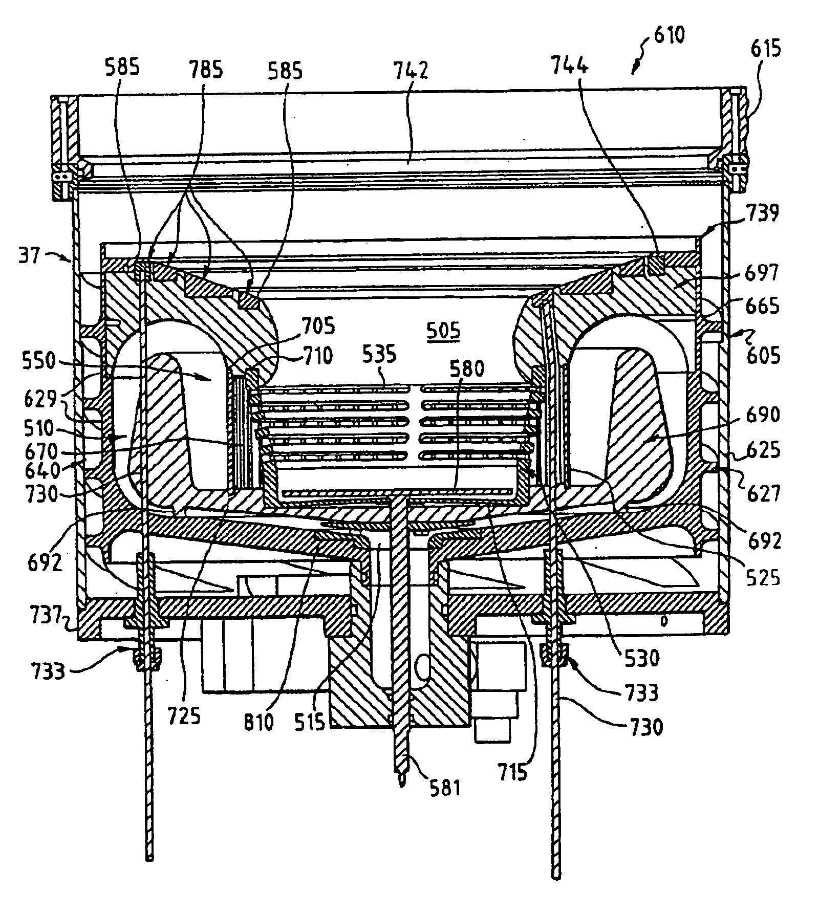
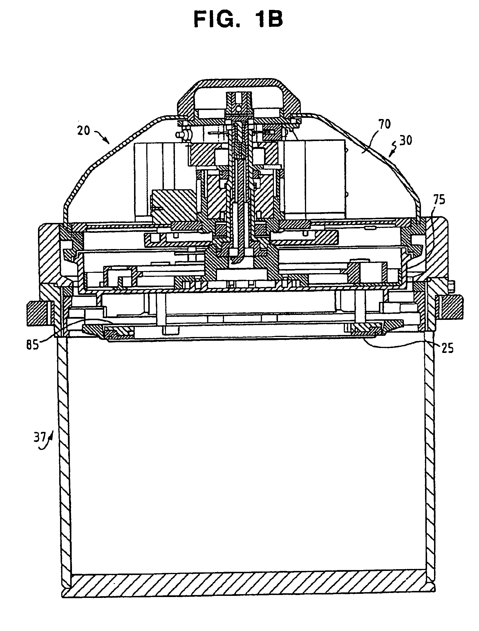
[0031] With reference to FIG. 1B, there is shown a reactor assembly 20 for electroplating a microelectronic workpiece 25, such as a semiconductor wafer. Generally stated, the reactor assembly 20 is comprised of a reactor head 30 and a corresponding reactor base, shown generally at 37 and described in substantial detail below, in which the electroplating solution is disposed. The reactor of FIG. 1B can also be used to implement electrochemical processing operations other than electroplating (e.g., electropolishing, anodization, etc.).

[0032] The reactor head 30 of the electroplating reactor assembly may comprised of a stationary assembly 70 and a rotor assembly 75. Rotor assembly 75 is configured to receive and carry an associated microelectronic workpiece 25, position the microelectronic workpiece in a process-side down orientation within a container of reactor base 37, and to rotate or spin the workpiece while joining its electrically-conductive surf...


PUM

PropertyMeasurementUnit
perimeteraaaaaaaaaa
conductiveaaaaaaaaaa
elevationaaaaaaaaaa

Abstract

A reactor for electrochemically processing at least one surface of a microelectronic workpiece is set forth. The reactor comprises a reactor head including a workpiece support that has one or more electrical contacts positioned to make electrical contact with the microelectronic workpiece. The reactor also includes a processing container having a plurality of nozzles angularly disposed in a sidewall of a principal fluid flow chamber at a level within the principal fluid flow chamber below a surface of a bath of processing fluid normally contained therein during electrochemical processing. A plurality of anodes are disposed at different elevations in the principal fluid flow chamber so as to place them at difference distances from a microelectronic workpiece under process without an intermediate diffuser between the plurality of anodes and the microelectronic workpiece under process. One or more of the plurality of anodes may be in close proximity to the workpiece under process. Still further, one or more of the plurality of anodes may be a virtual anode. The present invention also related to multi-level anode configurations within a principal fluid flow chamber and methods of using the same.

Description

CROSS-REFERENCE TO RELATED APPLICATIONS [0001] The present application is a continuation of prior International Application No. PCT / US00 / 10120, filed on Apr. 13, 2000 in the English language and published in the English language as International Publication No. WO00 / 61498, which in turn claims priority to the following three U.S. Provisional Applications: U.S. Ser. No. 60 / 129,055, entitled “WORKPIECE PROCESSOR HAVING IMPROVED PROCESSING CHAMBER”, filed Apr. 13, 1999; U.S. Ser. No. 60 / 143,769, entitled “WORKPIECE PROCESSING HAVING IMPROVED PROCESSING CHAMBER”, filed Jul. 12, 1999; U.S. Ser. No. 60 / 182,160 entitled “WORKPIECE PROCESSOR HAVING IMPROVED PROCESSING CHAMBER”, filed Feb. 14, 2000. The entire disclosures of all three of the prior applications, as well as International Publication No. WO00 / 61498, are incorporated herein by reference.STATEMENT REGARDING FEDERALLY SPONSORED RESEARCH OR DEVELOPMENT [0002] Not Applicable BACKGROUND OF THE INVENTION [0003] The fabrication of micr...

Claims


Application Information

Patent Timeline
Patent Type & Authority Applications(United States)
IPC IPC(8): C25D7/12B05C3/00B05C3/20B23H3/00C02FC25B9/00C25C7/00C25D3/02C25D5/00C25D5/04C25D5/08C25D7/00C25D11/32C25D17/00C25D17/02C25D17/12C25D21/00
CPCC25D5/08C25D17/001Y10S204/07C25D17/02C25F7/00C25D17/00
Inventor WILSON, GREGORY J.MCHUGH, PAUL R.HANSON, KYLE M.
Owner WILSON GREGORY J
Why Eureka
Try Eureka