Intensified hybrid solid-state sensor

a hybrid solid-state sensor and intensifier technology, applied in the field of intensified hybrid solid-state sensors, can solve the problems of sup>2 /sup>2 /sup>2 /sup>2 /sup>2 /sup>, and the image intensifier/isup>2 /sup>cameras suffer from numerous, object looking fuzzier,

Inactive Publication Date: 2005-08-04
ELBIT SYSTEMS OF AMERICA LLC
View PDF21 Cites 46 Cited by
  • Summary
  • Abstract
  • Description
  • Claims
  • Application Information

AI Technical Summary

Problems solved by technology

The result is that bright lights appear much brighter to a viewer of a solid-state system and tend to wash out the scene.
However, image intensifier / I2 cameras suffer from numerous disadvantages.
This results in the object looking fuzzier to the human observer, or solid-state sensor, when viewed through an image intensifier.
Another disadvantage with image intensifier / I2 cameras is “halo.” Halo results from electrons being reflected off either the MCP or the screen.
Nevertheless, the screen halo is still a significant defect in imaging systems when a CCD or CMOS array is coupled to the image intensifier.
Another disadvantage is that image intensifiers do not have a method of providing electronic read-out.
When a solid-state device is coupled to an image tube the resultant camera has all performance defects of the image tube that is low contrast, often poor limiting resolution due to coupling inefficiencies and the added cost of the image tube to the camera.
The disadvantages of an all solid-state device are poor low light level performance, potential blooming from bright light sources, poor limiting resolution, and high power consumption.
The poor low light performance is due to dark current and read-out noise resulting in low signal-noise ratios.
Solid-state device architectures usually do not permit an amplification section prior to read-out.
The poor limiting resolution is due to large pixel sizes usually chosen in an attempt to collect a large signal and thereby increase the signal to noise ratio.
These disadvantages have effectively prevented the use of solid-state sensors in night vision applications.
But the disadvantages are numerous.
Secondly, the sensor suffers “halo” degradation of the image around bright lights due to electrons reflected off of the solid-state sensor.
This halo exists in regular image tubes; however, technological improvements have reduced the halo to the point of non-existence.
Thirdly, the very high voltage required to operate the device (2-10 kV) damages the silicon surface causing decay in performance over time.

Method used


Image

  • Intensified hybrid solid-state sensor
  • Intensified hybrid solid-state sensor
  • Intensified hybrid solid-state sensor

Examples


Embodiment Construction

[0041] Preferred features of embodiments of this invention will now be described with reference to the figures. It will be appreciated that the spirit and scope of the invention is not limited to the embodiments selected for illustration. Also, it should be noted that the drawings are not rendered to any particular scale or proportion. It is contemplated that any of the configurations and materials described hereafter can be modified within the scope of this invention.

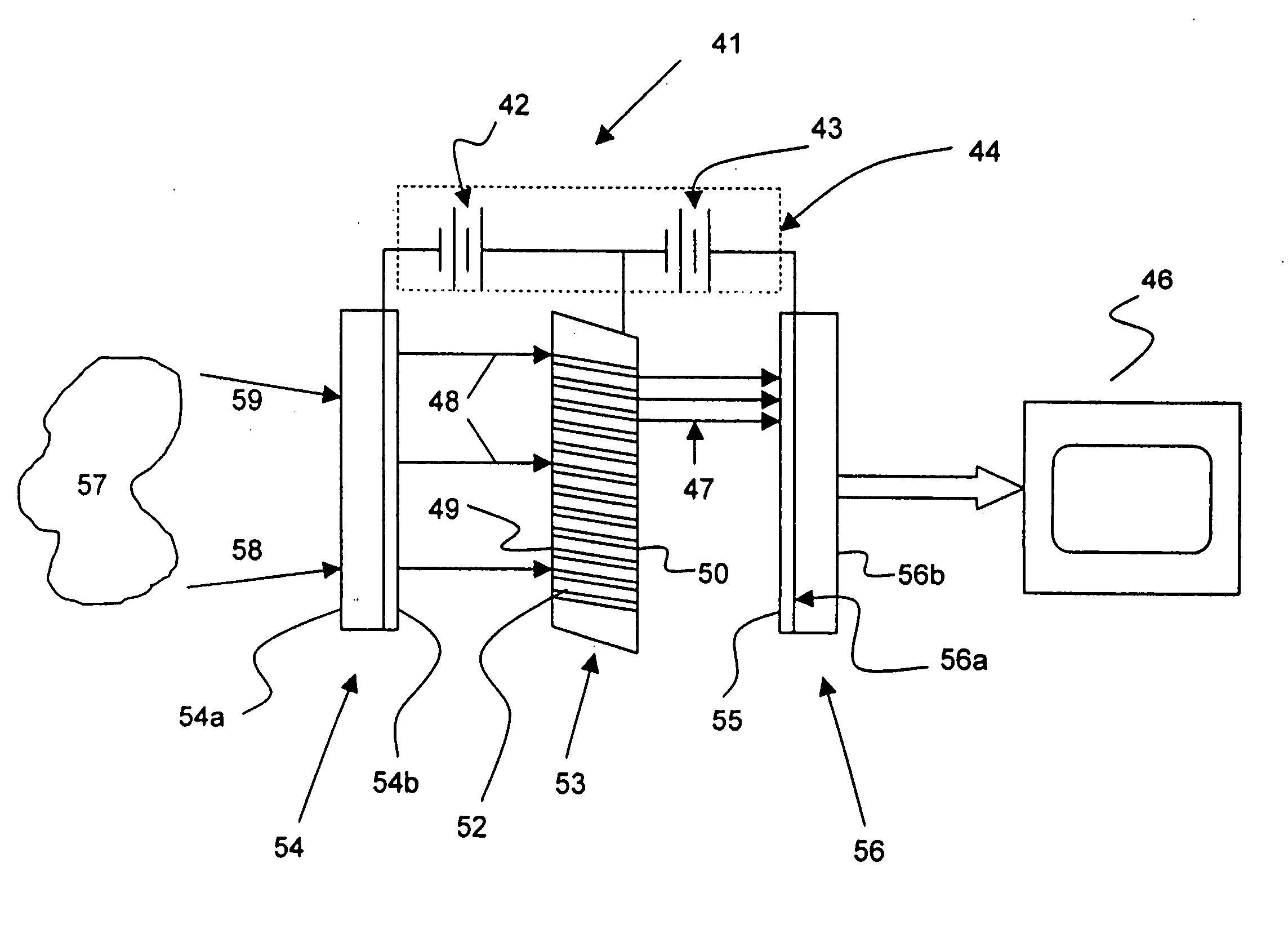
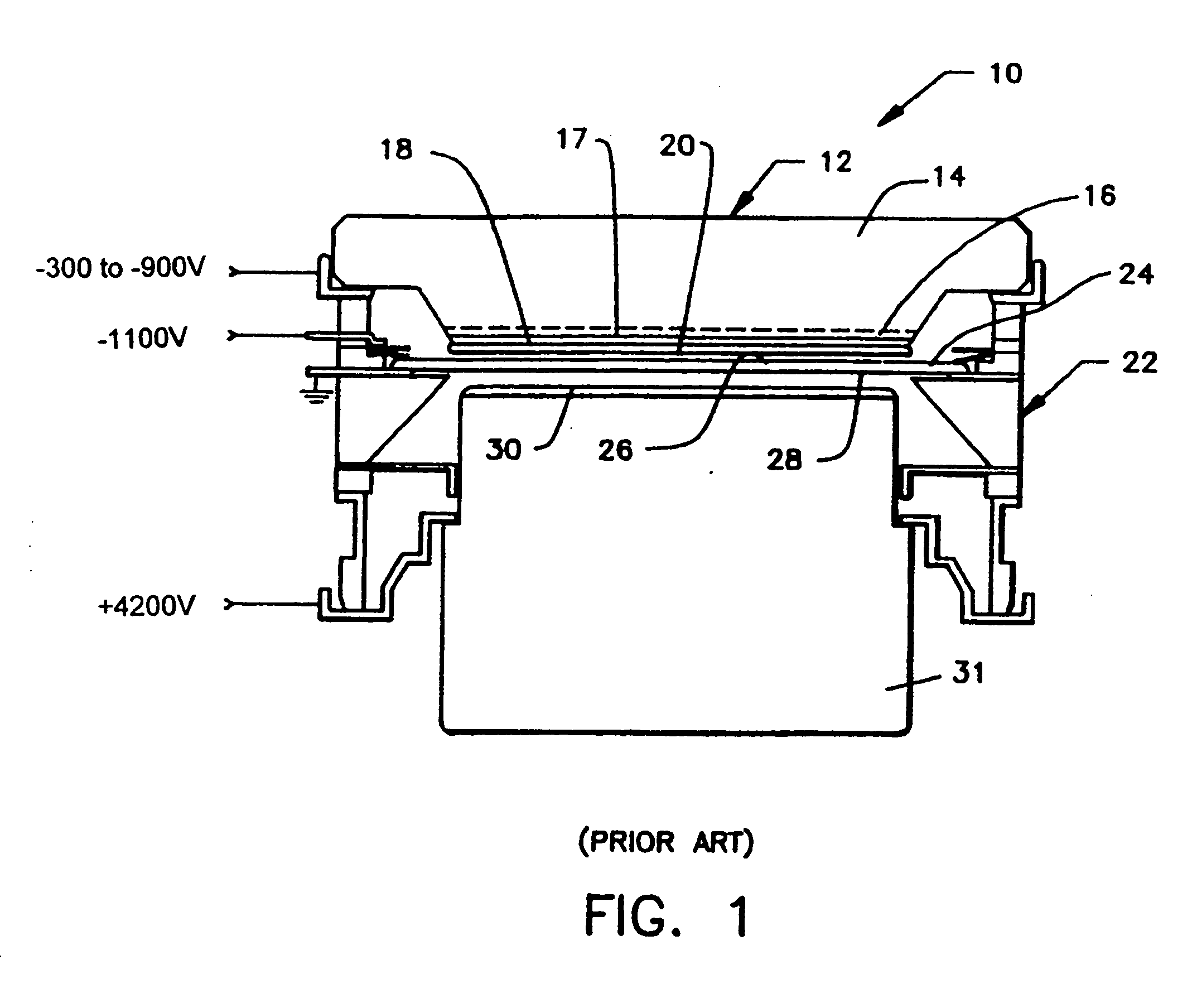
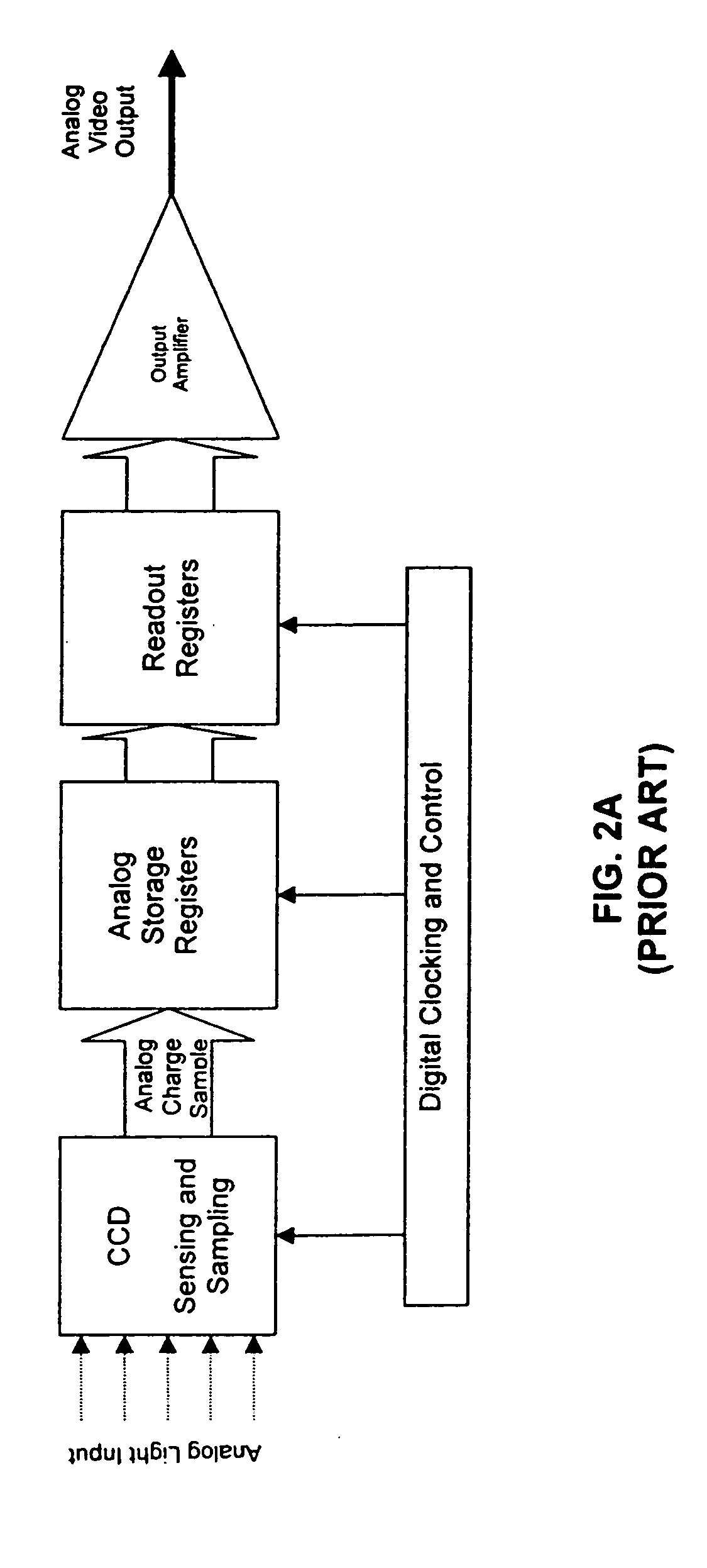
[0042] In copending U.S. patent application Ser. No. 09 / 973,907, the present invention was described as providing an intensified hybrid solid-state sensor. The solid-state sensor, according to the present invention, includes an imaging device comprising a solid-state sensor assembled with an image intensifier cathode, microchannel plate (MCP), and body envelope. This device combines the best functions of the image intensifier, good signal-to-noise ratio and high logarithmic gain, with the electronic read-out functions...


PUM


Abstract

An intensified solid-state imaging sensor includes a photo cathode for converting light from an image into electrons, an electron multiplying device for receiving electrons from the photo cathode, and a solid-state image sensor including a plurality of pixels for receiving the electrons from the electron multiplying device through a plurality of channels of the electron multiplying device. The solid-state image sensor generates an intensified image signal from the electrons received from the electron multiplying device. The plurality of channels are arranged in a plurality of channel patterns, and the plurality of pixels are arranged in a plurality of pixel patterns. Each of the plurality of channel patterns is mapped to a respective one of the plurality of pixel patterns such that electron signals from each of the plurality of channel patterns is substantially received by the single respective one of the plurality of pixel patterns.

Description

RELATED APPLICATION [0001] The present application is a continuation-in-part of pending U.S. patent application Ser. No. 09 / 973,907 filed on behalf of inventors Rudolph G. Benz, Nils I. Thomas, and Arlynn W. Smith on Oct. 9, 2001, titled INTENSIFIED HYBRID SOLID-STATE SENSOR WITH AN INSULATING LAYER, assigned to the assignee of the present application, and incorporated in this application by reference.FIELD OF THE INVENTION [0002] The present invention is directed to an intensified hybrid solid-state sensor. More particularly, the present invention relates to an image intensifier using a CMOS or CCD sensing device connected in close physical proximity to a microchannel plate (MCP) and photo cathode. BACKGROUND OF THE INVENTION [0003] The present invention relates to the field of image intensifying devices using solid-state sensors, such as a CMOS or CCD device. Image intensifier devices are used to amplify low intensity light or convert non-visible light into readily viewable images...

Claims


Application Information

Patent Timeline
Patent Type & Authority Applications(United States)
IPC IPC(8): H01J31/26H01L27/146H01J31/48H01J31/50H04N5/335
CPCH01J31/26H01J31/48H01J2231/5016H01J2231/50068H01J31/49G01T1/2957H01J31/50
Inventor BENZ, RUDOLPH G.THOMAS, NILS I.SMITH, ARLYNN W.
Owner ELBIT SYSTEMS OF AMERICA LLC
Why Eureka
Try Eureka