Modular pattern illumination and light beam multiplexing for selective excitation of microparticles

a microparticle and module pattern technology, applied in the field of optical microscopy imaging, can solve the problems of significant reduction of illumination efficiency, challenge the alignment of pattern channels, and complicate the system design, and achieve the effect of simplifying the layout of optical components

Active Publication Date: 2014-08-26
REBUS BIOSYSTEMS INC
View PDF6 Cites 15 Cited by
  • Summary
  • Abstract
  • Description
  • Claims
  • Application Information

AI Technical Summary

Problems solved by technology

This circumstance of intercrossing beams complicates the system design and challenges the pattern channel alignment.
As a result, each pattern channel utilizes only a small fraction of the full laser power to illuminate the target samples and the illumination efficiency is significantly reduced.

Method used


Image

  • Modular pattern illumination and light beam multiplexing for selective excitation of microparticles
  • Modular pattern illumination and light beam multiplexing for selective excitation of microparticles
  • Modular pattern illumination and light beam multiplexing for selective excitation of microparticles

Examples


Embodiment Construction

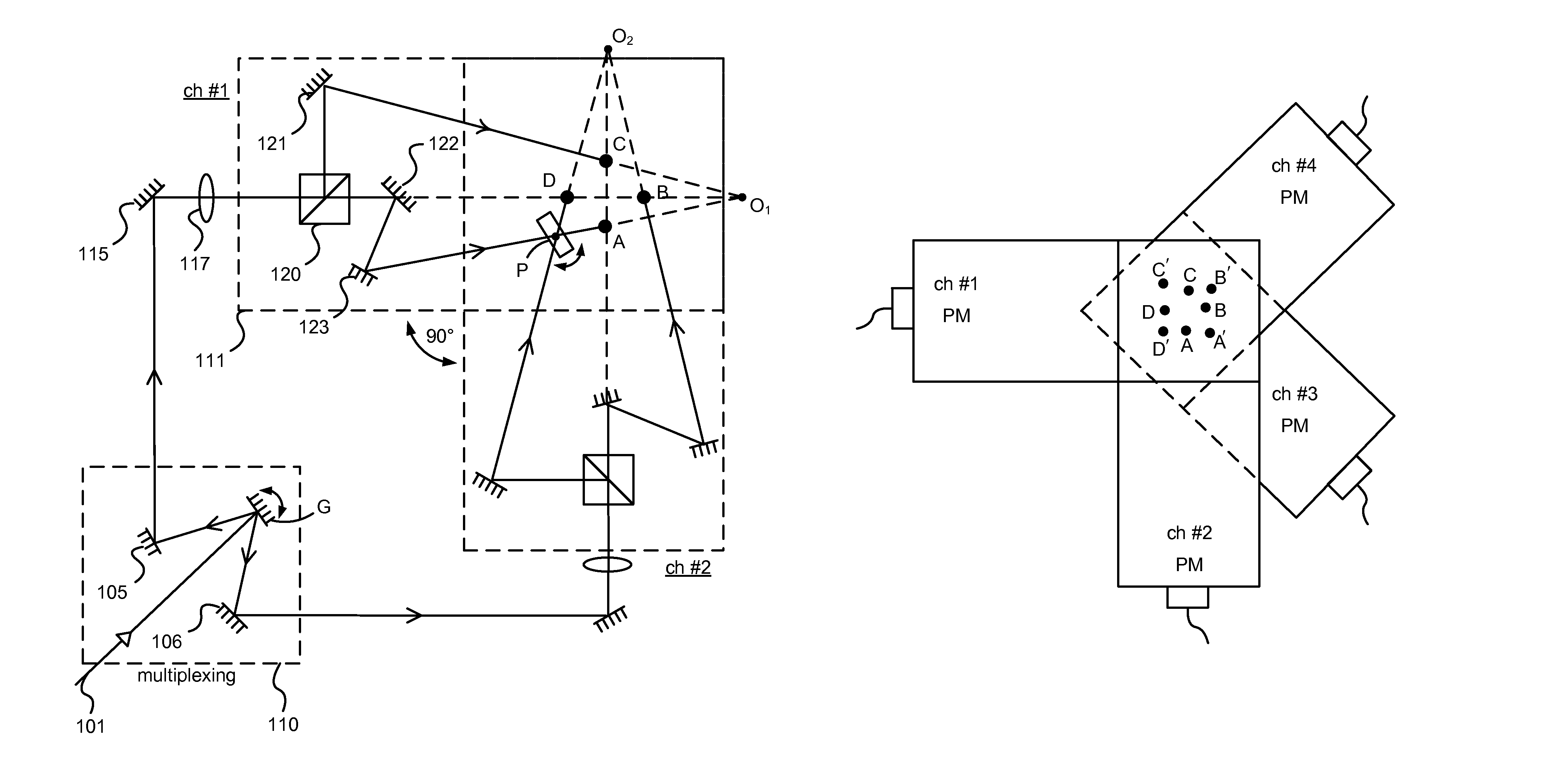
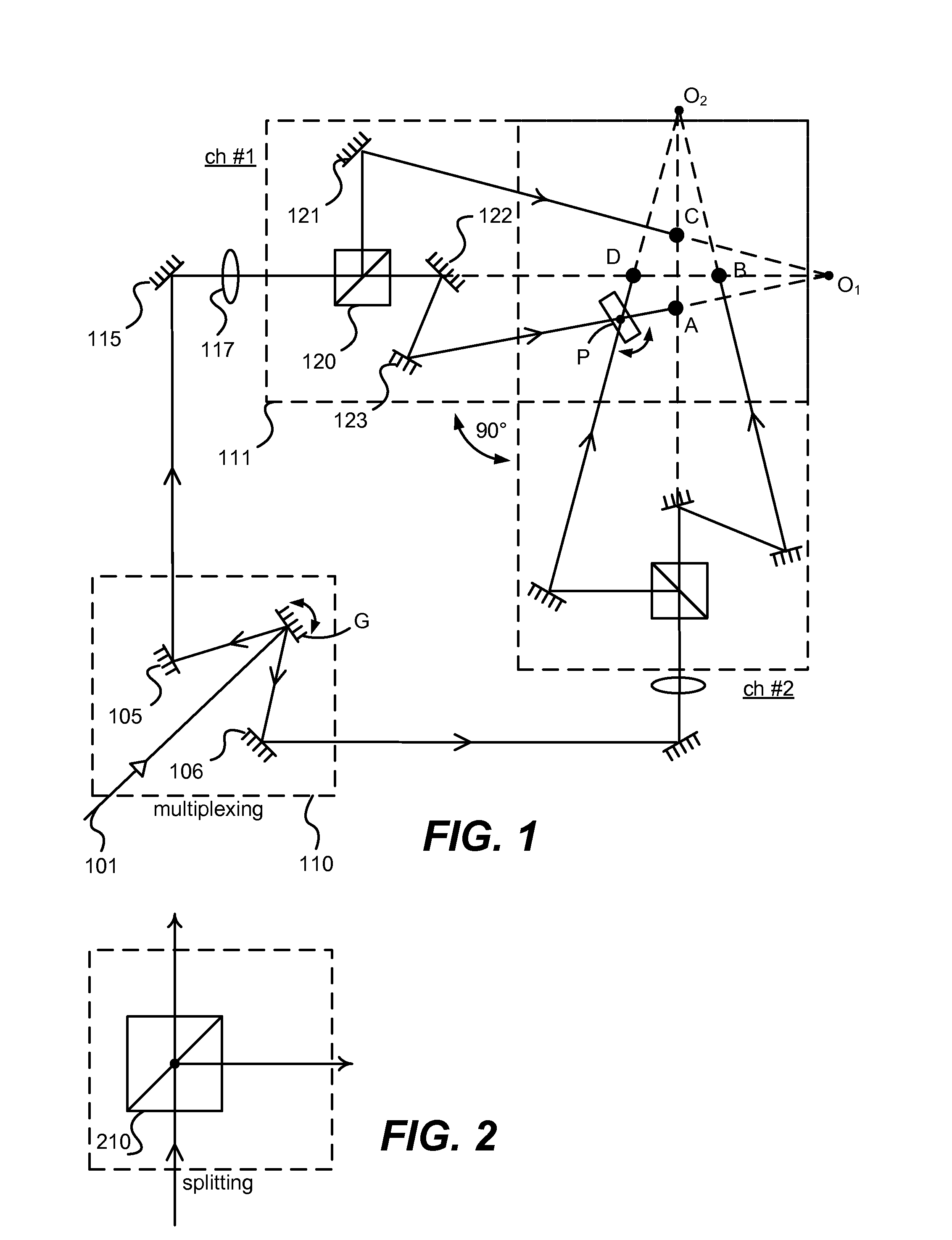
[0022]The present invention makes use of a modular configuration to implement a pattern illumination system of any desirable number of channels. FIG. 1 illustrates the configuration of the basic dual-channel pattern module in which two single-channel pattern modules within a common plane are oriented, for example, at 90 degrees from each other, but other non-zero offset angles between the pattern modules can be used in other examples. Similarly, in other examples, the pattern modules may not be in a common plane. In the example shown in FIG. 1, a galvo-scanner-based phase-shifting module P is shared between these two channels. By eliminating the need for a phase-shifting module for each channel separately, fewer optical components are used, resulting in a manufacturing cost savings. Also, in one implementation of the invention, no anamorphic beam expander is used, in contrast to implementations used before this invention.

[0023]As illustrated in FIG. 1, an optical beam 101 enters the...


PUM

PropertyMeasurementUnit
offset anglesaaaaaaaaaa
incident angleaaaaaaaaaa
offset anglesaaaaaaaaaa

Abstract

A modular approach to a pattern illumination system for selective excitation of microparticles is used. A dual-channel pattern module having two single-channel pattern modules are oriented at a non-zero offset angle to each other. In this arrangement, a galvo-scanner based phase-shifting module is shared between the two channels. A set of tilt mirrors are used to direct the beams from the pattern modules onto the target plane. Additional layers of pattern modules can be added to accommodate any desirable number of additional channels. The additional layer(s) may be rotationally off-set from the other layer(s) by an angular amount to simplify the layout of optical components. A remote light source module may be connected to the pattern modules through optical fiber.

Description

GOVERNMENT LICENSE RIGHTS[0001]This invention was made with government support under grant number R44HG005127-02 (for “Deep-Submicron Optical Detection for High-Density High-Throughput DNA Sequencing”) awarded by the National Institutes of Health. The government has certain rights in the invention.CROSS-REFERENCE TO RELATED APPLICATION(S)[0002]This application claims priority to U.S. Provisional Application No. 61 / 480,637, filed Apr. 29, 2011, titled “Modular Pattern Illumination and Light Beam Multiplexing for Selective Excitation of Microparticles,” and this application is related to U.S. patent application Ser. No. 11,846,067, filed Aug. 28, 2007, titled “Apparatus for Selective Excitation of Microparticles,” both of which are incorporated by reference in their entirety.BACKGROUND[0003]1. Field of the Invention[0004]This invention generally relates to the field of optical microscopy imaging which uses selective illumination or excitation. More specifically, this invention relates...

Claims


Application Information

Patent Timeline
Patent Type & Authority Patents(United States)
IPC IPC(8): G02F1/29
CPCG02B26/06G02B21/06
Inventor LEE, CHUN-SHEU
Owner REBUS BIOSYSTEMS INC
Why Eureka
Try Eureka