
Reformer for fuel cell system and method of manufacturing reaction substrate used for the same

a fuel cell and reaction substrate technology, applied in the field of reformers comprising reaction substrates, can solve problems such as thermal conduction disadvantages and system inability to be compactly implemented

Inactive Publication Date: 2005-11-17
SAMSUNG SDI CO LTD
View PDF2 Cites 15 Cited by
  • Summary
  • Abstract
  • Description
  • Claims
  • Application Information

AI Technical Summary

Benefits of technology

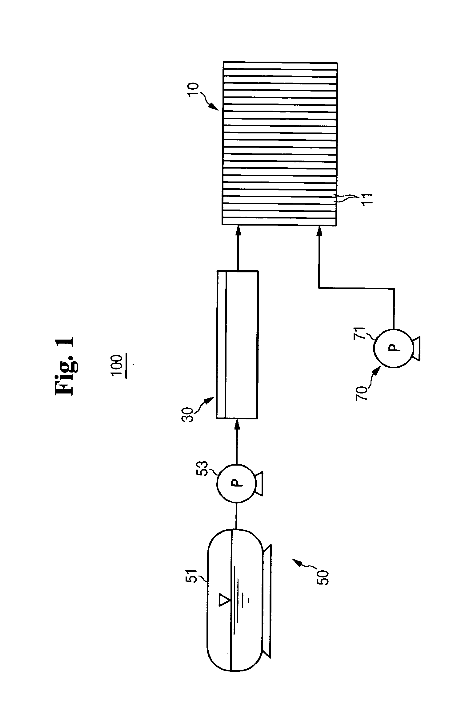
[0016] The reformer of a fuel cell system may further comprise at least one carbon monoxide reducing unit similar to the reaction substrates for the reforming unit and the heat source unit. The carbon monoxide reducing unit defines a plurality of flow channels, each with a carbon monoxide reducing catalyst layer. The carbon monoxide reducing unit reduces the concentration of carbon monoxide contained in the hydrogen fed to the electricity generating unit and is in close contact with the heat source unit.

Problems solved by technology

In a conventional reformer of a fuel cell system, since the heat source unit and the reforming unit are formed in a vessel shape and are connected to each other through pipes, the heat is not exchanged directly between the respective reaction units, thereby causing a disadvantage in thermal conduction.
In addition, since the respective reaction units are separate, the system cannot be implemented compactly.

Method used


Image

  • Reformer for fuel cell system and method of manufacturing reaction substrate used for the same
  • Reformer for fuel cell system and method of manufacturing reaction substrate used for the same
  • Reformer for fuel cell system and method of manufacturing reaction substrate used for the same

Examples


example

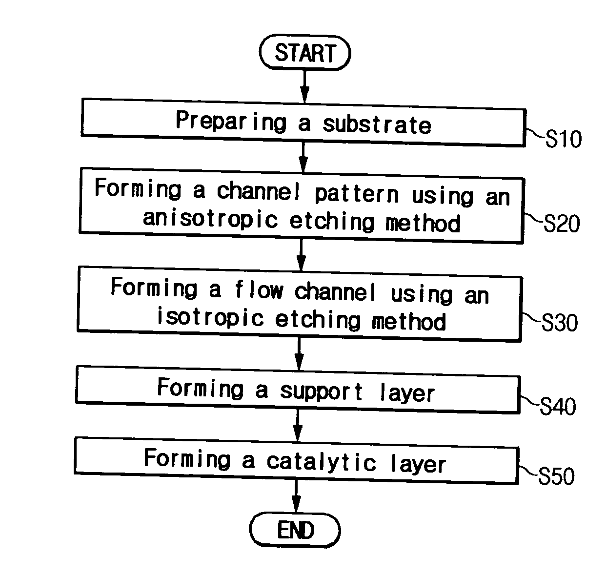
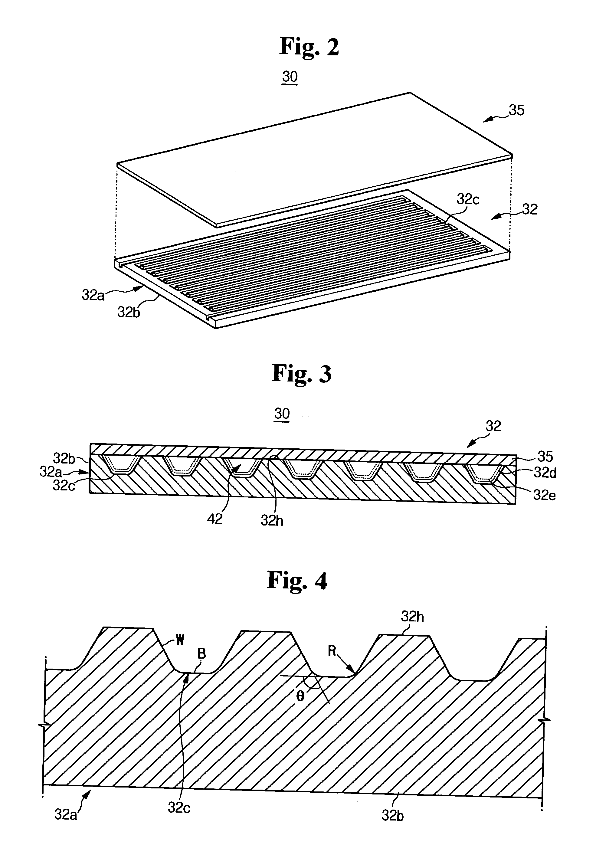
[0065] A silicon (Si) substrate was prepared with a mask for defining a channel pattern. Then, an anisotropic etching process was performed on the upper surface of the substrate body at a temperature of 80° C. for 2 hours by using a 30 wt % KOH solution. A channel pattern of which the bottom portion and the wall portions form right angles was formed on the upper surface of the substrate body through the anisotropic etching process. Next, an isotropic etching process was performed on the channel pattern at room temperature for 0.5 to 4 minutes by using an etchant obtained by mixing NF, H2O, and HNO3 at a ratio of 1:1:8. As a result, a plurality of flow channels were formed such that the joints between the bottom portion and the wall portions of each flow channel are rounded and the angles between the bottom portion and the wall portions form obtuse angles. Thereafter, by using aluminum isopropoxide as a precursor and using a 0.07 mol HCL peptization agent and a 3 g / 100 mol PVA (PolyV...


PUM

PropertyMeasurementUnit
Angleaaaaaaaaaa
Radiusaaaaaaaaaa
Angleaaaaaaaaaa

Abstract

There is provided a reformer for a fuel cell system, the reformer comprising: a reforming unit having a reaction substrate in which a catalyst layer is formed in a plurality of flow channels for allowing fuel to flow and for generating hydrogen through a reformation reaction of the fuel using thermal energy. When viewing a cross-section perpendicular to the flow direction of the flow channels, the reaction substrate defines each flow channel by a bottom portion and a pair of wall portions extending from the sides of the bottom portion, and a joint between the bottom portion and the wall portion is formed in a rounded shape. There is also provided a method of manufacturing a reaction substrate used for a reformer for a fuel cell system, the method comprising: (a) preparing a substrate; (b) anisotropically etching the upper surface of the substrate and forming a channel pattern of which a bottom portion and a wall portion are perpendicular to each other; (c) isotropically etching the channel pattern and forming a flow channel of which the joints between the bottom portion and the wall portions are rounded; (d) forming a support layer on the surface of the flow channel; and (e) forming a catalyst layer on the support layer.

Description

CROSS REFERENCE TO RELATED APPLICATION [0001] This application claims priority to and the benefit of Korean Patent Application No. 10-2004-0034212 filed on May 14, 2004 in the Korean Intellectual Property Office, the entire content of which is incorporated herein by reference. FIELD OF THE INVENTION [0002] The present invention relates to a reformer for a fuel cell system and more particularly to a reformer comprising a reaction substrate. BACKGROUND OF THE INVENTION [0003] In general, a fuel cell is an electricity generating system that generates electric energy through an electrochemical reaction between oxygen and hydrogen or hydrogen contained in hydrocarbon materials such as methanol, ethanol, or natural gas. [0004] A polymer electrolyte membrane fuel cell (hereinafter, referred to as PEMFC) has been developed recently which has excellent output characteristics, low operating temperatures, and fast starting and response characteristics. PEMFCs have a wide range of application i...

Claims


Application Information

Patent Timeline
IPC IPC(8): B23P15/00C01B3/32C01B3/38H01M8/06H01M8/10
CPCH01M8/0631Y02E60/50H01M2008/1095H01M8/0668Y02P70/50H04M1/17H04M1/0237
Inventor KIM, JU-YONGKWEON, HO-JINKIM, JAE-JEONGKWON, OH-JOONG
Owner SAMSUNG SDI CO LTD
Learn More