Dimmer circuit with improved ripple control

a ripple control and circuit technology, applied in the direction of automatic controllers, welding electric supplies, resistance welding apparatuses, etc., can solve the problems of unsatisfactory flickering of lamp intensity and suffer from conduction angle timing variations, so as to reduce the effect of mains rippl

Inactive Publication Date: 2005-08-04
CLIPSAL INTEGRATED SYST
View PDF13 Cites 33 Cited by
  • Summary
  • Abstract
  • Description
  • Claims
  • Application Information

AI Technical Summary

Benefits of technology

[0008] According to the present invention, there is provided a mains ripple injection filter for reducing the effects of mains ripple in a phase-controlled dimmer c...

Problems solved by technology

In many dimmer circuit designs the presence of mains ripple injection results in undesirable lamp intensity flickering.
Typical dimmer designs utiliz...

Method used


Image

  • Dimmer circuit with improved ripple control
  • Dimmer circuit with improved ripple control
  • Dimmer circuit with improved ripple control

Examples


Embodiment Construction

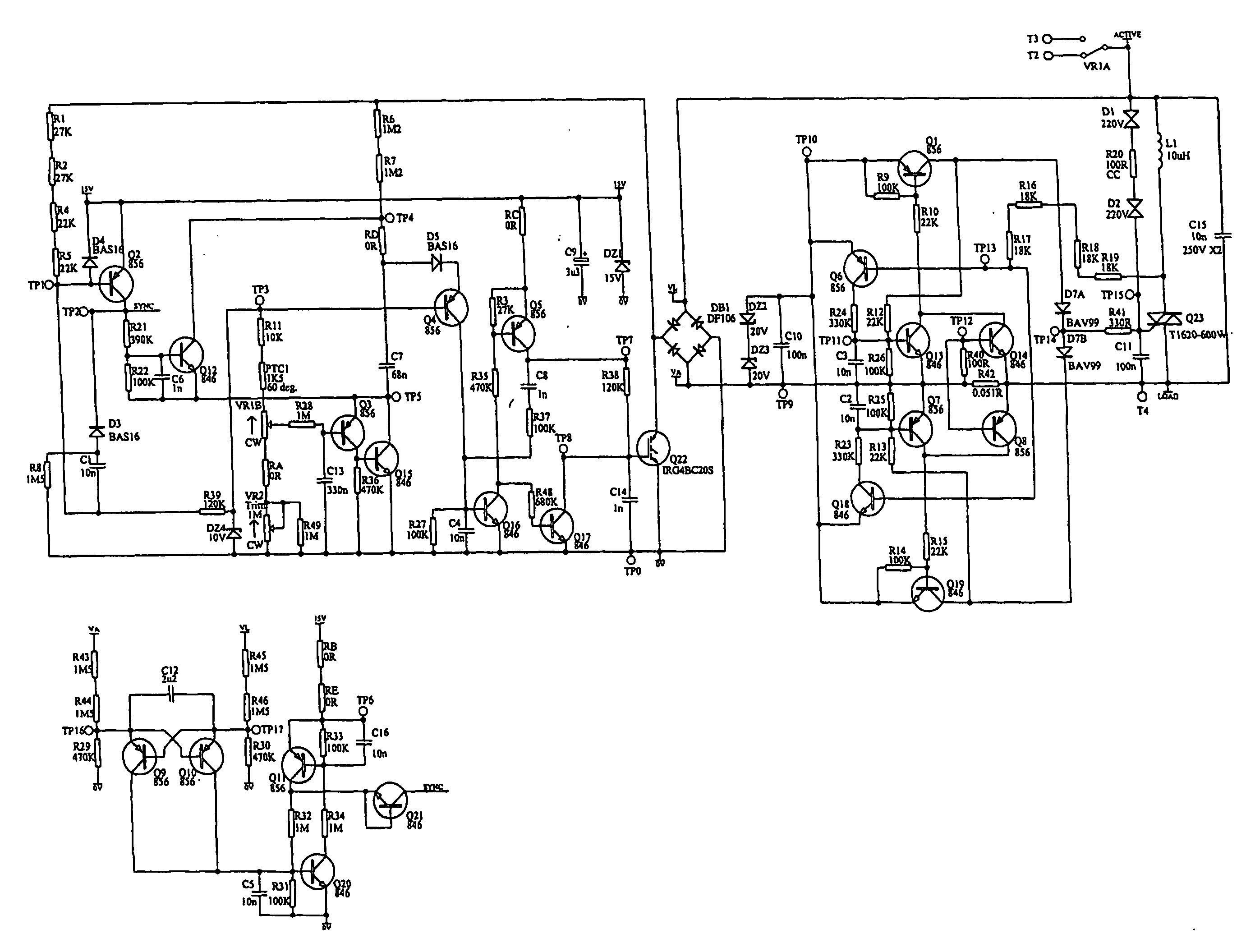
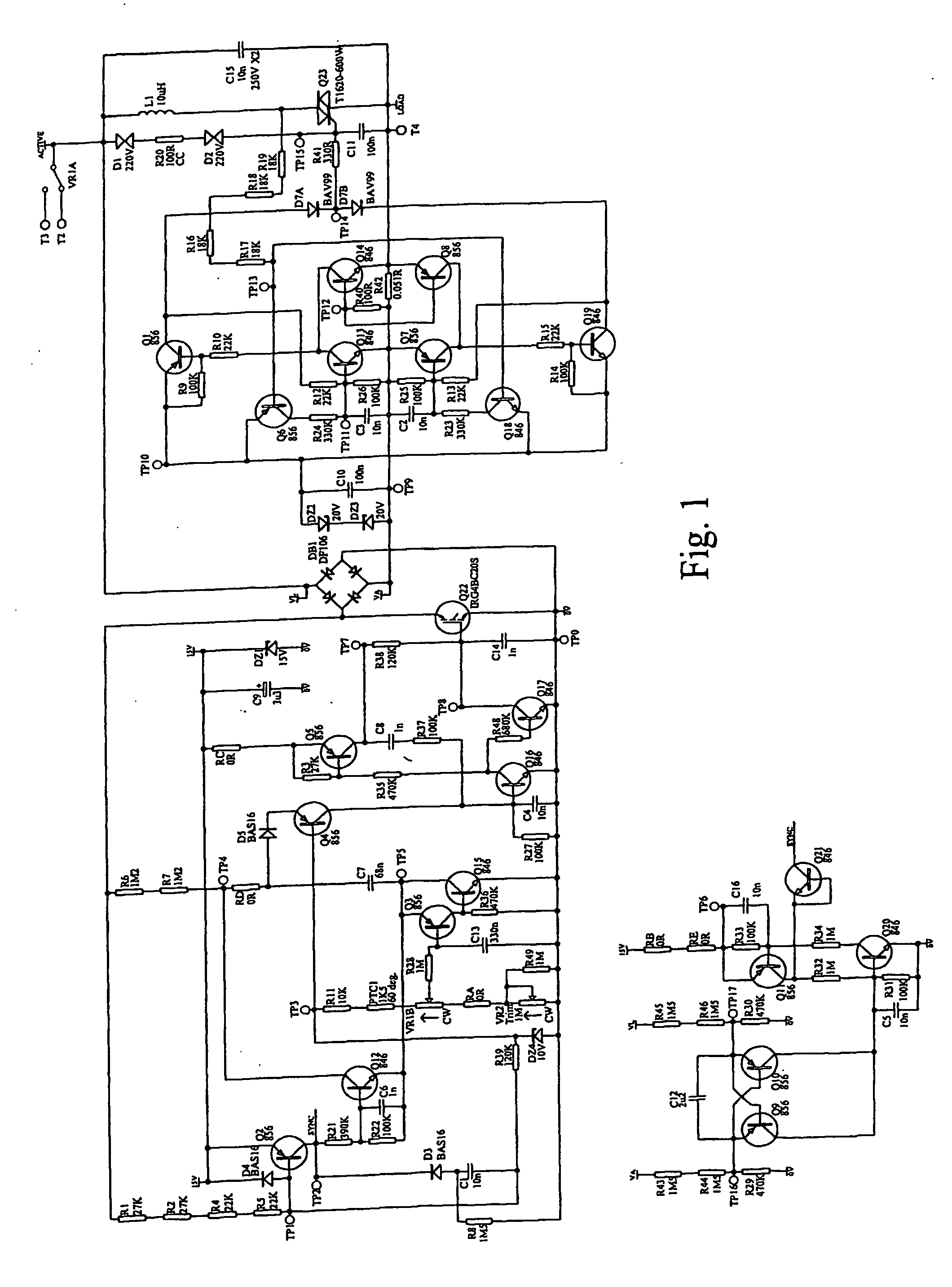
[0016] A preferred circuit design of a 2-wire, leading edge phase control light dimmer / fan speed controller is shown in FIG. 1. The design shown in FIG. 1 is particularly effective in that it is electromagnetic compatible (EMI compliant). This refers to the amount of electromagnetic interference (EMI) that is generated by the circuit. The amount of radiation generated by dimming circuits due to high frequency switching of the circuit is heavily regulated and such circuits must not exceed the regulated level of EMI.

[0017] The circuit design of FIG. 1 controls the level of EMI generated by the circuit via active control of the rate of rise of load voltage at each main half cycle. A power semiconductor in the form of an IGBT is used for this function. The IGBT and associated drive control circuitry is connected to the DC side of a diode bridge to allow control of polarities of voltage.

[0018] A power triac is used to handle the load current once the IGBT as performed the required slow...


PUM

PropertyMeasurementUnit
Angleaaaaaaaaaa
Electric potential / voltageaaaaaaaaaa
Conductionaaaaaaaaaa

Abstract

A dimmer circuit arrangement is disclosed including a second control circuit for controlling the operation of a triac for delivering current to a load, and a first control circuit for controlling the operation of an IGBT power semiconductor switch for controlling the rate of rise of load voltage. The first control circuit also controls the operation of the second control circuit.

Description

TECHNICAL FIELD [0001] This invention relates to circuit arrangements for controlling the power provided to a load and in particular, to dimmer circuits for controlling, for example, the luminosity of a light or the speed of a fan. BACKGROUND TO THE INVENTION [0002] Dimmer circuits are used to control the power provided to a load such as a light or electric motor from a power source such as mains. Such circuits often use a technique referred to as phase controlled dimming. This allows power provided to the load to be controlled by varying the amount of time that a switch connecting the load to the power source is conducting during a given cycle. [0003] For example, if voltage provided by the power source can be represented by a sine wave, then magnum power is provided to the load if the switch connecting the load to the power source is on at all times. In this way the the total energy of the power source is transferred to the load. If the switch is turned off for a portion of each c...

Claims


Application Information

Patent Timeline
IPC IPC(8): G05F5/02H02M7/12H02M1/08H02M1/15H03K17/13H03K17/16H05B1/00H05B39/04H05B39/08H05B41/24H05B41/38H05B47/10
CPCH02M1/081H02M1/15H02M1/40H02M5/2573H02H3/253H05B39/08Y02B20/148Y10S315/04H05B39/048Y02B20/00G05F5/00
Inventor VANDERZON, JAMES ROBERT
Owner CLIPSAL INTEGRATED SYST
Why Eureka
Try Eureka