Scanning Rangefinder

a rangefinder and scanning technology, applied in the field of scanning rangefinders, can solve the problems of restrictions on the installation of rangefinders, the damage of the structure of scanning rangefinders of fig. 9 and other problems, to achieve the effect of shortening the inter-optic-axial separation and shortening the inter-axial separation

Active Publication Date: 2005-08-04
HOKUYO AUTOMATIC CO +1
View PDF18 Cites 81 Cited by
  • Summary
  • Abstract
  • Description
  • Claims
  • Application Information

AI Technical Summary

Benefits of technology

[0013] An object of the present invention is in a scanning rangefinder to shorten the inter-optic-axial separation between the optical axis of the scanning beam directed at a subject, and the optical axis of the received subject-reflected rays taken into the rangefinder sensor. Thus shortening the inter-axial separation enables the rangefinder to be made so as not to give rise to a blind spot even with respect to subjects at close range.

Problems solved by technology

Nevertheless, scanning rangefinders of the FIG. 9 structure suffer from the following drawbacks.
2) Because the center of the optical system is the center of the rangefinder, and the rangefinder is vertically extensive, restrictions on how the rangefinder may be installed result.

Method used


Image

  • Scanning Rangefinder
  • Scanning Rangefinder
  • Scanning Rangefinder

Examples


Embodiment Construction

[0043] In the following, an explanation of modes of embodying, and modified embodiments, of the present invention will be made with reference to the accompanying drawings.

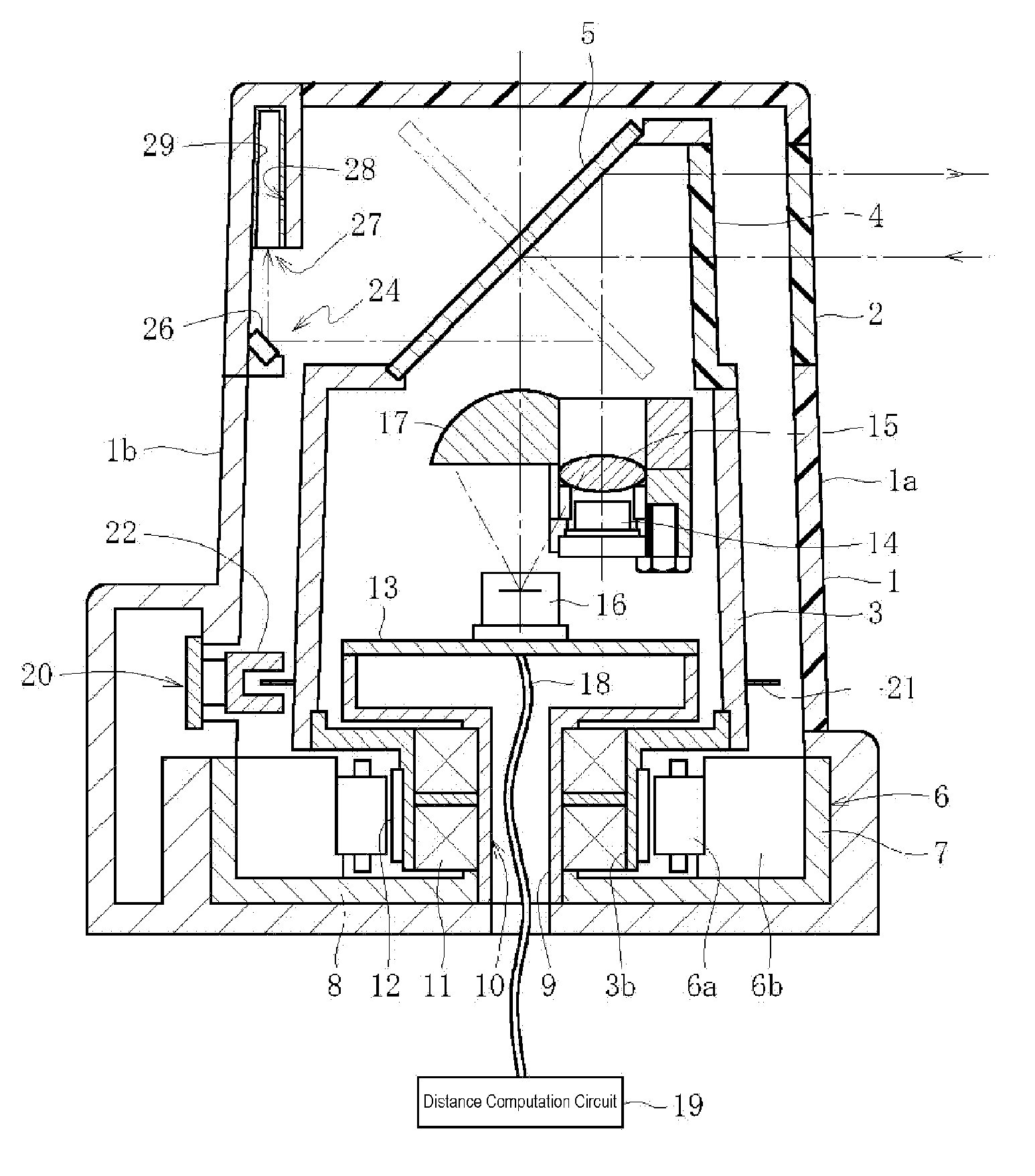
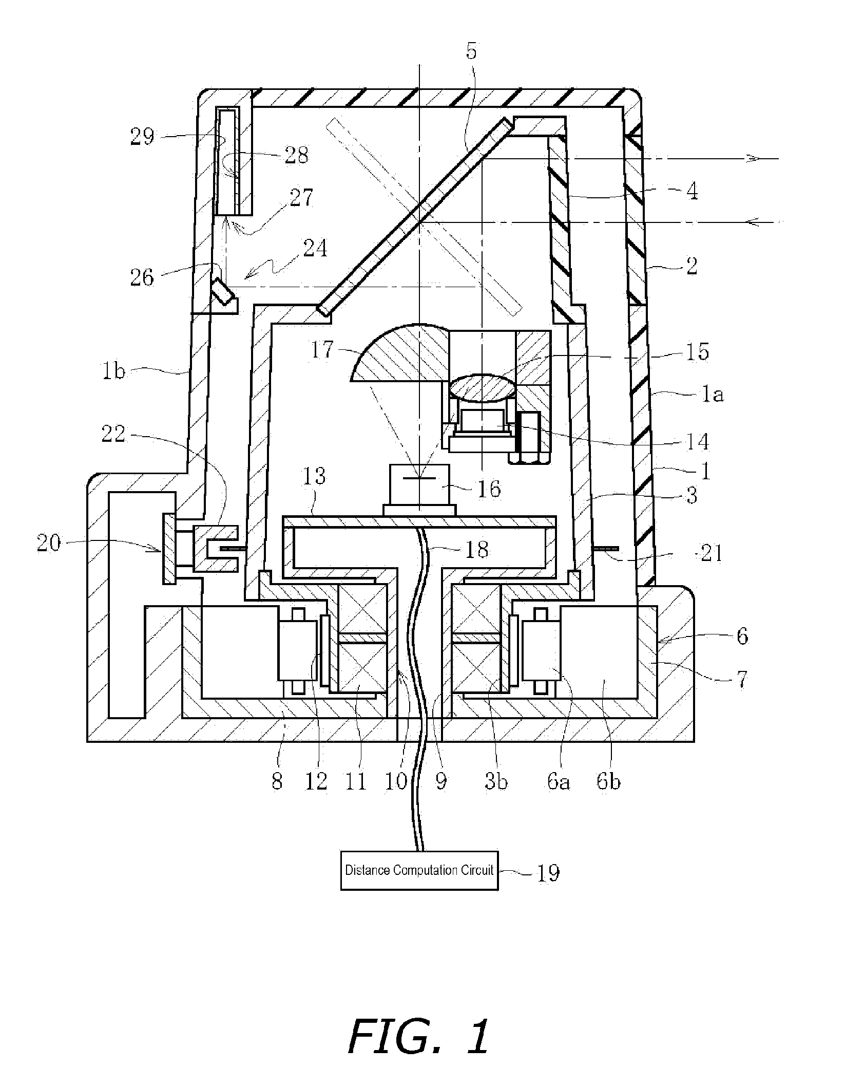
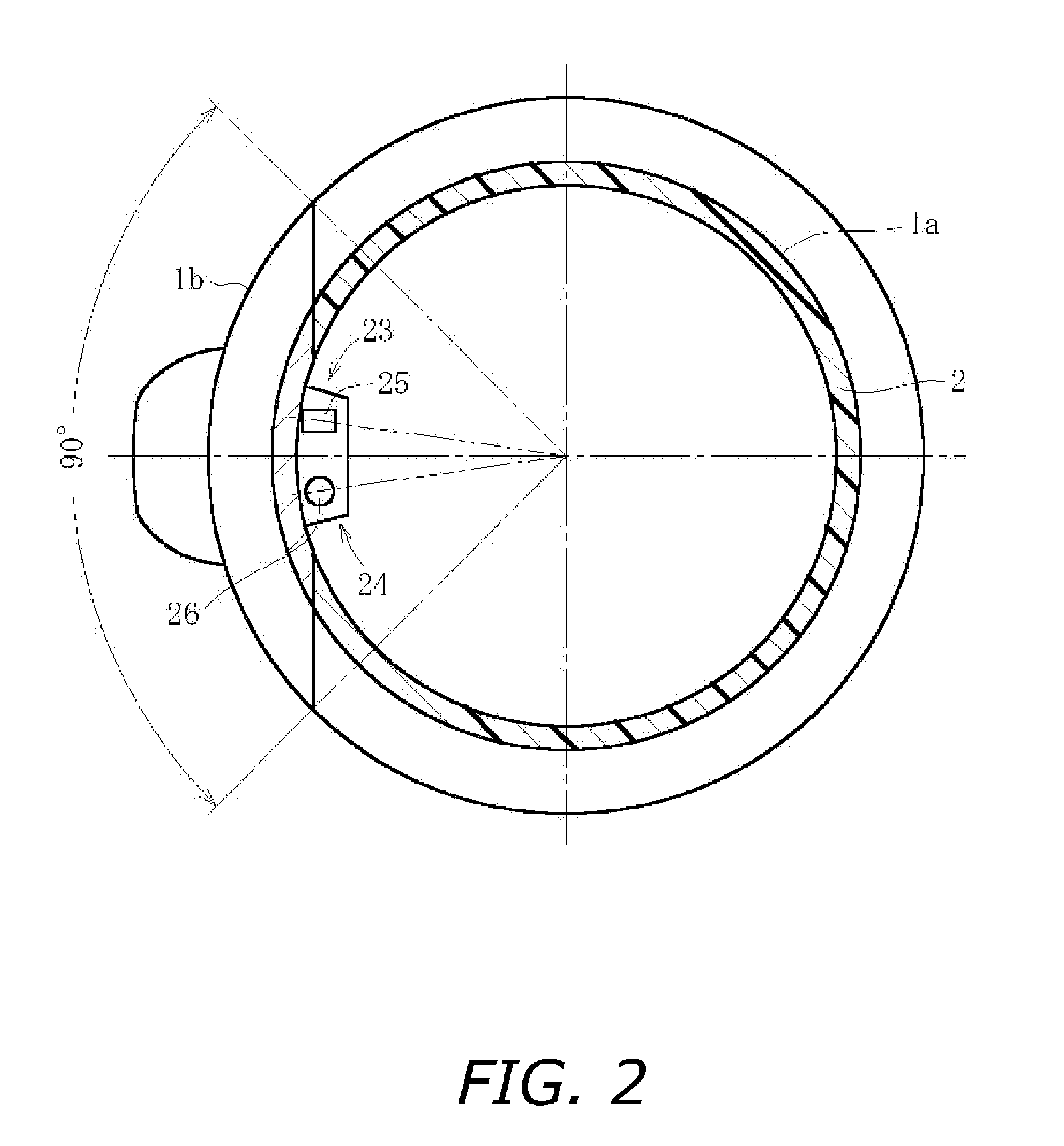
[0044] Embodiment 1—FIGS. 1 and 2 illustrate a single example of a mode of embodying the present invention, in an implementation in which visible light is applied as the electromagnetic radiation, wherein reference numeral 1 in FIG. 1 indicates an outer cover (1) in the form of a round vertical frustum. The scanning rangefinder main unit is housed within the outer cover 1. In instances in which a scanning rangefinder of the present invention is utilized in a security robot or in a robotic vacuum cleaner, the outer cover 1 will be carried in the crown portion of such robots. The outer cover 1 includes a first member 1a constituted by a suitable material such as a synthetic polymeric resin, and a second member 1b constituted by an opaque material such as metal or an appropriate synthetic polymeric resin. As illustra...


PUM

PropertyMeasurementUnit
angleaaaaaaaaaa
rightward angleaaaaaaaaaa
power consumptionaaaaaaaaaa

Abstract

Scanning rangefinder of simple, compact construction. The rangefinder is furnished with: an outer cover (1) in which a transparent window (2) is formed; a cylindrical rotary unit (3) inside the outer cover (1); a scanning/receiving window (4) provided in the rotary unit (3); a dual scanning/receiving mirror (5) disposed, angled, along the rotational axis of the cylindrical rotary unit (3); a motor (6) for rotationally driving the rotary unit (3); a disk part (13) arranged in the cylindrical rotary unit (3), anchored in an inside region thereof; a beam projector (14) anchored in a location where it is disposed slightly spaced apart from the rotational axis of the rotary unit (3); and a light receiver (16) anchored to, arranged coincident with the rotational axis of, the disk part (13) in the inside region of the rotary unit (3), and connected to a distance computation circuit (19).

Description

BACKGROUND OF THE INVENTION [0001] 1. Technical Field [0002] The present invention relates to so-called scanning rangefinders, designed to informationally receive, with an electromagnetic wave receiver connected to a distance computation circuit, reflection of electromagnetic waves that from an electromagnetic wave projector have been directed onto and scanned over scanning targets, and to computationally gauge the distance to the scanning targets. [0003] 2. Description of the Related Art [0004] To date, two configurations, as represented in FIGS. 9 and 10, have been known for scanning rangefinders that use a rotating mirror(s) and wobble its optical axis over an entire 360-degree circuit. In either configuration the optical axis of the mirror(s) and the shaft of the motor that rotates the mirror(s) are made coincident. [0005] The rangefinder in FIG. 9 is structured to employ a double-shaft motor 42 from which common rotary shafts 41a and 41b are jutted out vertically, with a scanni...

Claims


Application Information

Patent Timeline
Patent Type & Authority Applications(United States)
IPC IPC(8): G01S17/32G01S7/48G01S7/481G01S7/497G01S17/36G01S17/42
CPCG01S7/4812G01S7/4813G01S17/42G01S7/497G01S17/36G01S7/4817
Inventor YAMASHITA, MAKOTOKIZUKURI, HIROSHITSUKUDA, SHINICHIMORI, TOSHIHIRO
Owner HOKUYO AUTOMATIC CO
Why Eureka
Try Eureka