Aperture stop device

a stop device and aperture technology, applied in the direction of microscopes, instruments, camera diaphragms, etc., can solve the problems of low resolution capability and a lower level of light power for the microscop

Active Publication Date: 2005-08-04
CARL ZEISS SURGICAL
View PDF9 Cites 29 Cited by
  • Summary
  • Abstract
  • Description
  • Claims
  • Application Information

AI Technical Summary

Benefits of technology

[0021] The aperture stop device can also include an input unit which is connected to the memory and / or the control unit for inputting a relationship which is to be stored and which associates a number of aperture signals with a number of values of the observation parameter. Input of a new relationship permits the microscope to be adapted to fresh requirements so that the microscope is to be used in a particularly flexible manner.

Problems solved by technology

In order to increase the depth of focus the aperture must be reduced in size, which however results in a lower resolution capability and a lower level of light power for the microscope.

Method used


Image

  • Aperture stop device
  • Aperture stop device

Examples


Embodiment Construction

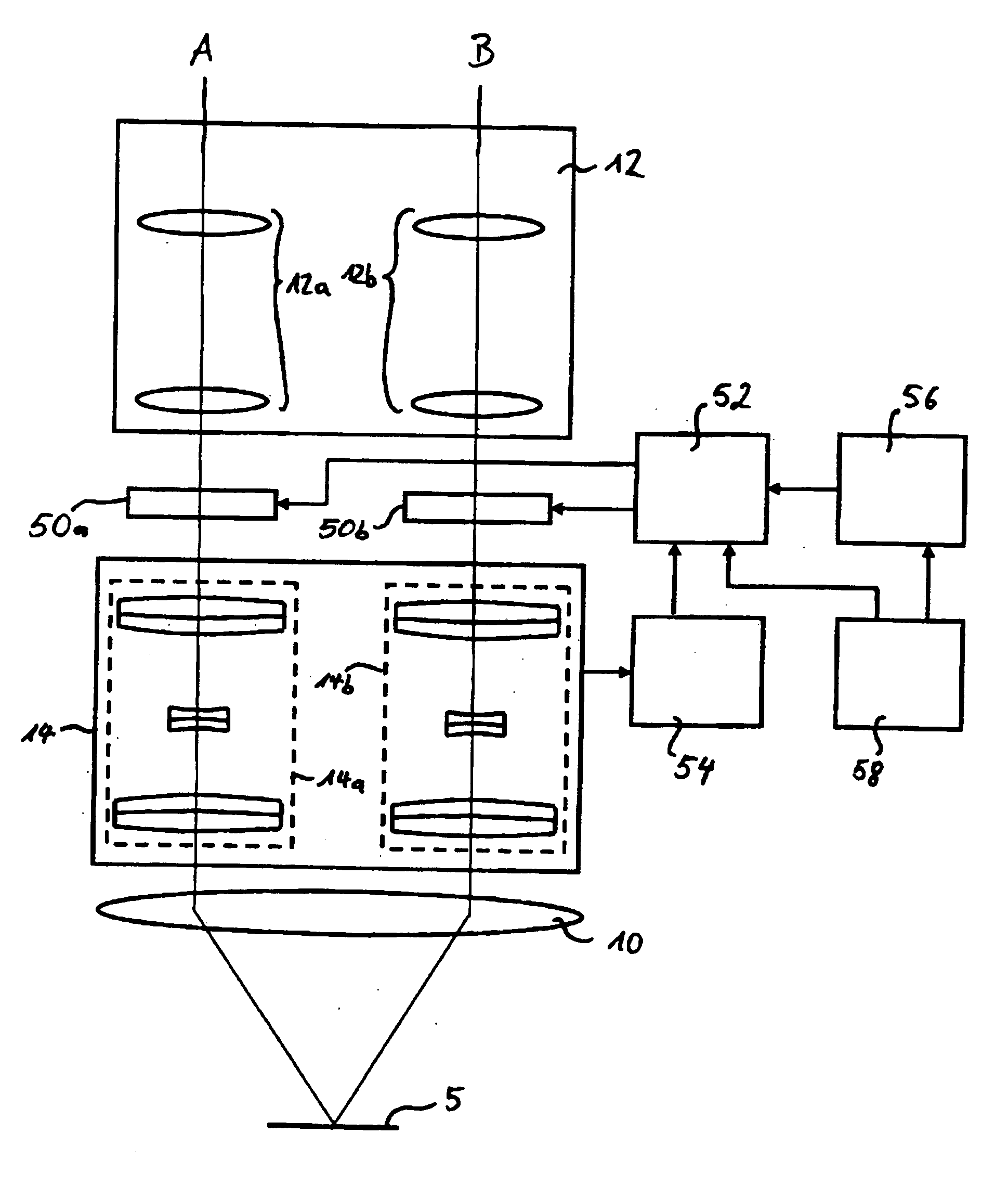
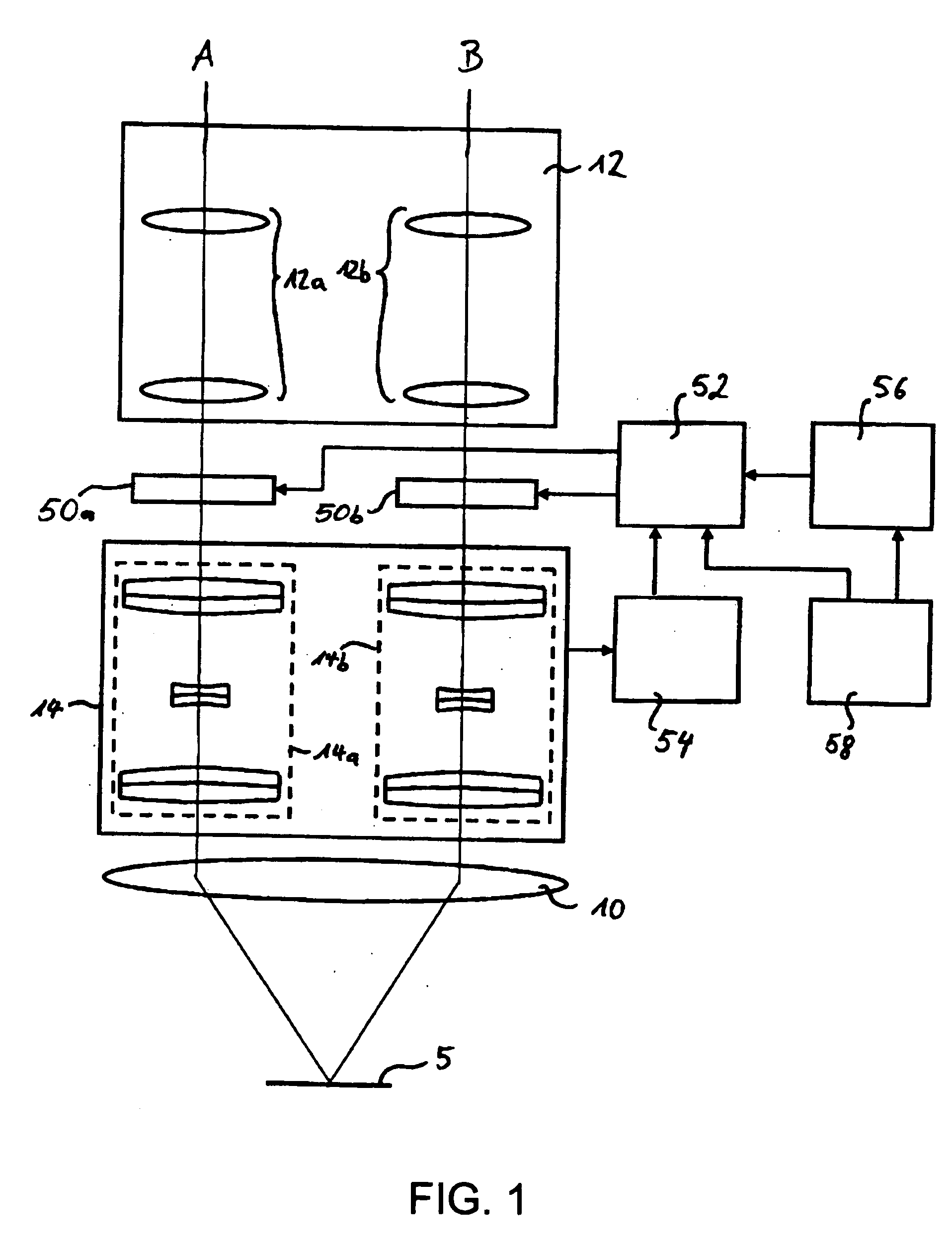
[0030] An operating microscope with an aperture stop device according to the invention is diagrammatically illustrated in FIG. 1 as an embodiment by way of example of the present invention.

[0031] The operating microscope includes an objective optical member 10 which is to face towards the region 5 of an operation, also referred to as the site of an operation, and a binocular optical system 12 which includes a first optical portion 12a for a first stereoscopic partial beam path A and a second optical portion 12b for a second stereoscopic partial beam path B. Connected downstream of the objective 10 in the beam path and arranged upstream of the binocular optical system 12 is a zoom system 14 with which the magnification factor of the microscope can be steplessly adjusted within a given range which generally includes magnification factors of between 0.4 and 2.5. Together with the objective focal length and the eyepiece focal length, the magnification factor determines the magnificatio...


PUM


Abstract

An aperture stop device is provided for use in a microscope with at least one adjustable observation parameter. The aperture stop device includes at least one aperture stop (50a, 50b) with an adjustable aperture, that is to say with an adjustable stop opening. The aperture stop (50a, 50b) is adapted to receive an aperture signal representative of an aperture to be adjusted. In addition the aperture stop device includes a control unit (52) for output of the aperture signal to the aperture stop (50a, 50b) in dependence at least on the respectively set value of the observation parameter of the microscope.

Description

BACKGROUND OF THE INVENTION [0001] 1. Field of the Invention [0002] The present invention concerns an aperture stop device for use in a microscope, in particular in an operating microscope, with an adjustable magnification factor, a microscope, in particular an operating microscope, having a device for adjusting the magnification factor and an aperture stop device according to the invention and a method of adjusting an optical property of a microscope with an adjustable magnification factor. [0003] 2. Description of the Related Art [0004] Microscopes and in particular stereoscopic operating microscopes have in the beam path behind the main objective a magnification changer with which different magnification factors can be implemented. The change in magnification can then be effected, while retaining the eyepiece, by changing the magnification factor by means of the magnification changer so that there is no need for a change in the eyepiece for altering the magnification. Zoom system...

Claims


Application Information

Patent Timeline
Patent Type & Authority Applications(United States)
IPC IPC(8): G02B21/20G02B5/00G02B21/00G02B21/06G02B21/22G03B9/02G03B9/07
CPCG02B21/06G02B5/005G02B21/22
Inventor MOLLER, GERHARDANDREWS, PETERREIMER, PETER
Owner CARL ZEISS SURGICAL
Why Eureka
Try Eureka