Method for the electron-microscopic observation of a semiconductor arrangement and apparatus therefor

a semiconductor and electron microscopic technology, applied in the field of electron microscopic observation of semiconductor arrangements, can solve the problems of difficult image of structures with a high aspect ratio significant number of such secondary electrons cannot enter the objective of the microscope, and the inability to satisfactorily image deeper structures by means of sem

Active Publication Date: 2004-04-08
CARL ZEISS SMT GMBH
View PDF17 Cites 31 Cited by
  • Summary
  • Abstract
  • Description
  • Claims
  • Application Information

AI Technical Summary

Problems solved by technology

However, it has been found that it is difficult to image structures with a high aspect ratio by means of a SEM, because secondary electrons which emanate from bottoms of deeper regions of the structures are absorbed by the walls of such structures.
As a result, a significant number of such secondary electrons cannot enter the objective of the microscope.
Therefore, deeper structures cannot be satisfactorily imaged by means of a SEM.
Due to this charging, artifacts are deliberately generated in the imaging of the semiconductor structure.
It can thus be concluded from these artifacts the presence of manufacturing defects of the structure with a high aspect ratio, for example, a hole.
This is because the artifacts cause a hole fabricated with a defect to appear in the electron-microscopy image larger or smaller than a hole corresponding to the specification.
However, this method does not provide a satisfactory image of the hole bottom either.
As a result, electrons, such as secondary electrons emitted with a motion component transverse to the surface normal, are prevented from traveling large paths transversely to the surface normal, and, as a result, from producing an excessive and uncompensatable image blur.
It was assumed

Method used


Image

  • Method for the electron-microscopic observation of a semiconductor arrangement and apparatus therefor
  • Method for the electron-microscopic observation of a semiconductor arrangement and apparatus therefor
  • Method for the electron-microscopic observation of a semiconductor arrangement and apparatus therefor

Examples


Embodiment Construction

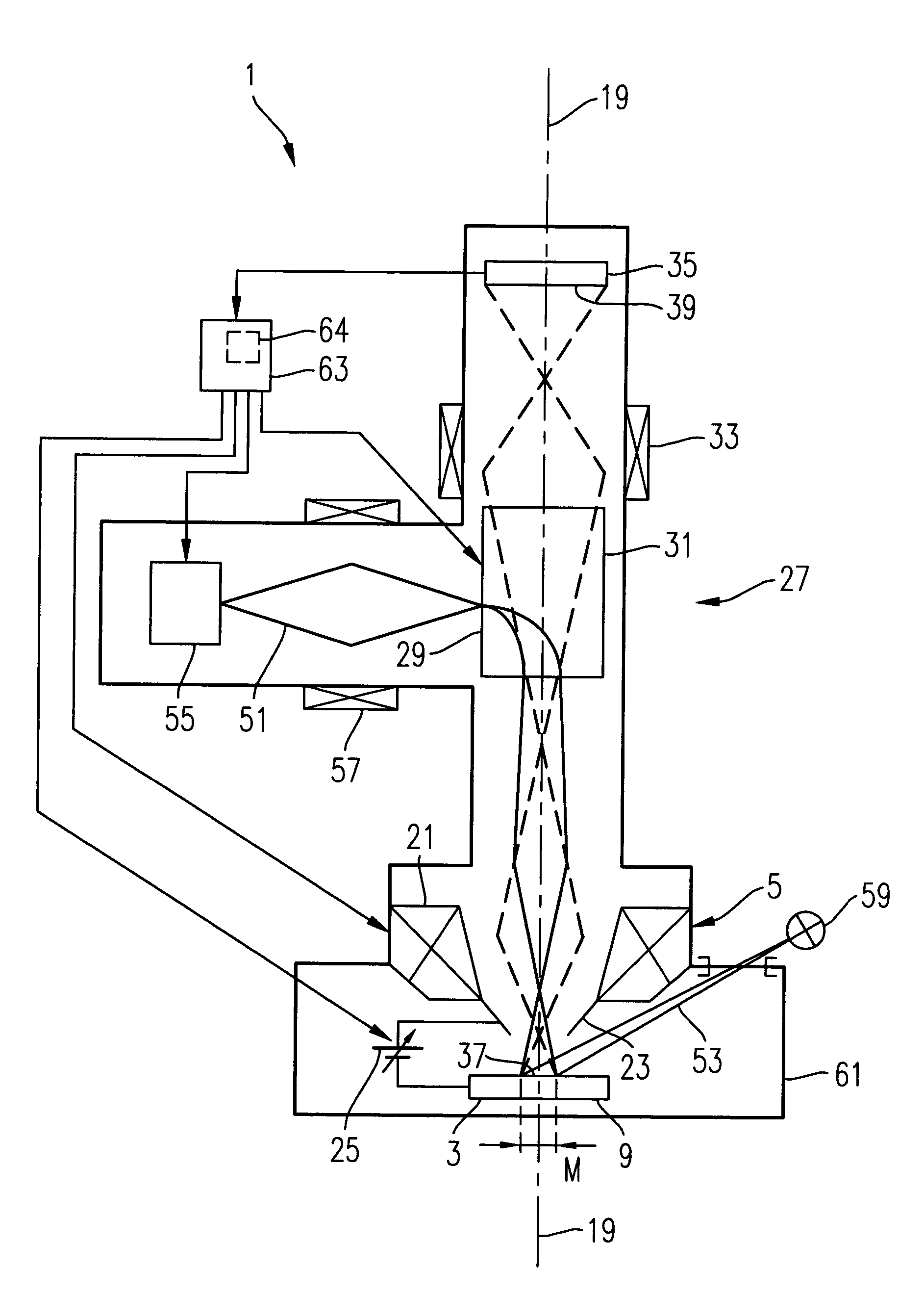
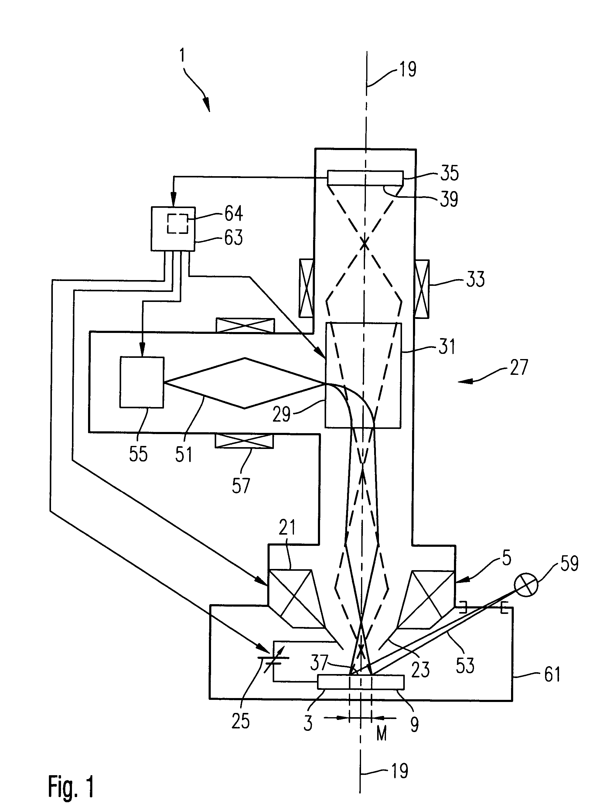
[0058] FIG. 1 schematically shows an electron microscope 1 which is suitable for implementing the method according to the invention. The electron microscope 1 serves to examine a semiconductor structure 3 which is positioned as object to be examined in front of an objective system 5 of the electron microscope 1.

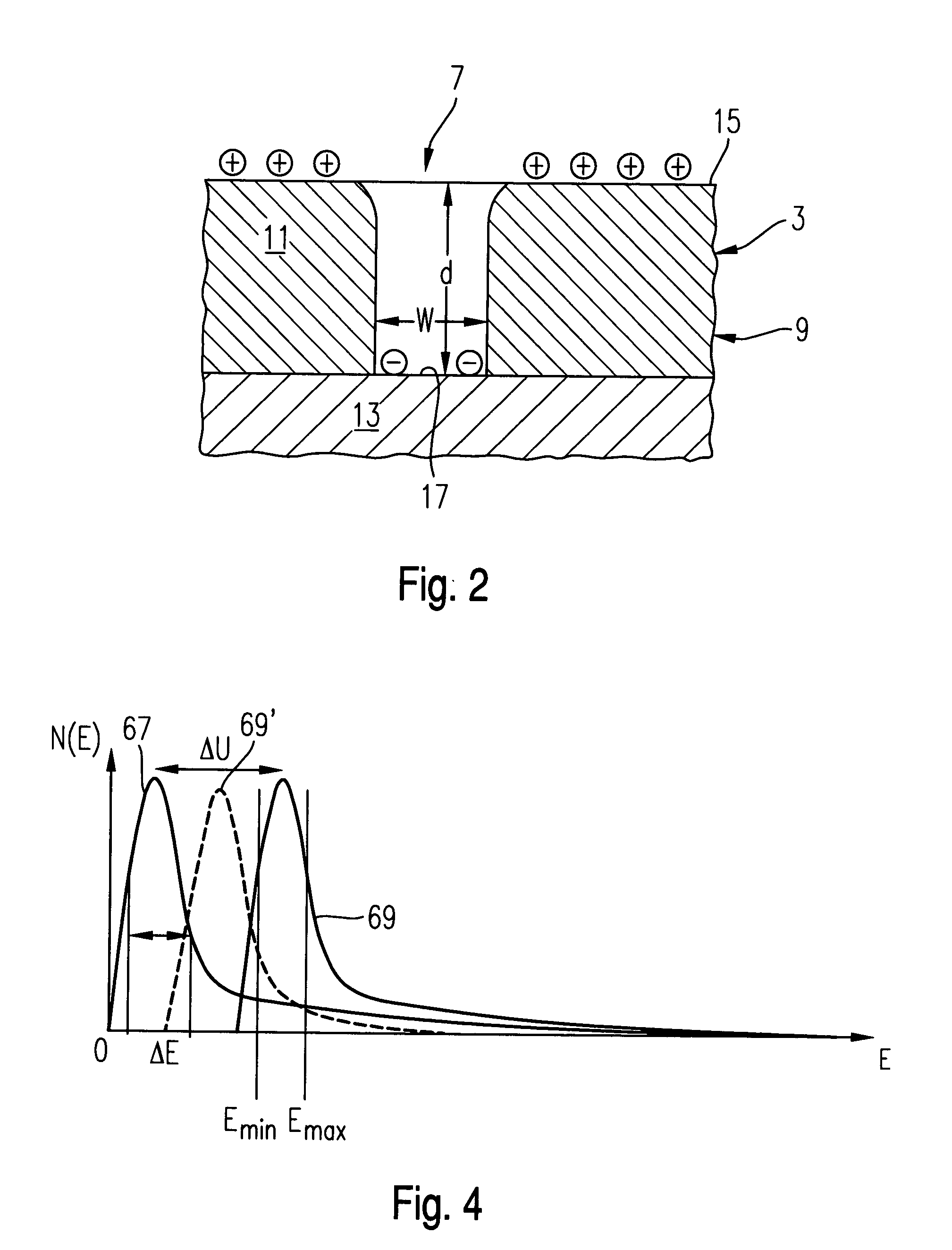
[0059] The semiconductor arrangement 3 constitutes, for example, a part of a semiconductor wafer or the like and has a topology comprising structures with a high aspect ratio, as it is shown schematically in FIG. 2 with reference to a recess 7. The structure 3 shown in FIG. 2 forms part of a semiconductor wafer 9 and comprises a layer 11 of SiO.sub.2 of a thickness d of, for example, 2.5 .mu.m which is deposited on a layer 13 of a metal, such as copper, for example. The SiO.sub.2 layer 11 has an upper surface 15 which faces towards the objective system 5 of the microscope 1. The recess 7 is formed in the SiO.sub.2 layer 11 and extends from the surface 15 through the SiO.sub.2...


PUM


Abstract

A method for the electron-microscopic observation of a semiconductor arrangement is provided. It includes providing an electron microscopy optics for imaging secondary electrons emanating from the semiconductor arrangement within an extended object field on a position-sensitive detector, providing an illumination device for emitting a primary energy beam, directing the primary energy beam to at least the object field for extracting there secondary electrons from the semiconductor arrangement. The semiconductor arrangement comprises a region with an upper surface provided by a first material and a recess with a high aspect ratio which is surrounded by the upper surface and has a bottom provided by a second material.

Description

[0001] 1) Field of the Invention[0002] The invention relates to a method for the electron-microscopic observation of a semiconductor arrangement having a topology with a high aspect ratio. The invention further relates to an apparatus for observing such a semiconductor arrangement.[0003] 2) Brief Description of Related Art[0004] Structures with a high aspect ratio are usually encountered in semiconductor manufacture. These are, for example, contact holes, trenches, etc.[0005] In order to image semiconductor structures and, in particular, in order to visualize defects in such semiconductor structures during manufacture, electron-microscopic methods are conventionally employed.[0006] A very common method in this respect is to image semiconductor structures by means of a scanning electron microscope "SEM". However, it has been found that it is difficult to image structures with a high aspect ratio by means of a SEM, because secondary electrons which emanate from bottoms of deeper regio...

Claims


Application Information

Patent Timeline
IPC IPC(8): H01L21/66G01N23/00G01N23/225G01Q20/00G01Q30/02G01Q30/04G21K7/00H01J37/05H01J37/244H01J37/28H01J37/29
CPCH01J2237/2817H01J37/28
Inventor KIENZLE, OLIVERKNIPPELMEYER, RAINERMULLER, INGO
Owner CARL ZEISS SMT GMBH
Why Eureka
Try Eureka