Network controlling apparatus and path controlling method therein

a network control and path technology, applied in electrical devices, digital transmission, data switching networks, etc., can solve the problems of inability to manage the communication quality of each path, inability to reserve along a route in the whole network, and inability to give consideration to techniques, etc., to improve the efficiency optimize the use rate of network resources, and reduce the overhead of the path setting process

Inactive Publication Date: 2005-08-04
FUJITSU LTD
View PDF5 Cites 61 Cited by
  • Summary
  • Abstract
  • Description
  • Claims
  • Application Information

AI Technical Summary

Benefits of technology

[0038] According to this invention, the controlling unit appropriately arranges a generated path every hour with a change in section and bandwidth requested in each time period while referring to contents of the storing unit, thereby flexibly generating a path according to the state of occurrence of requests. Therefore, it is possible to improve efficiency of the path setting process and optimize the use rate of the network resource. When it is desired to assign the resource along the optimum route in response to a quality guarantee request of a reservation type, a path already assigned for a quality guarantee request is used when it is determined appropriate to use the pa

Problems solved by technology

In this system, only a bandwidth of a link connected to the ATM exchange is reserved in response to a request, thus a reservation along a route in the whole network is impossible.
Namely, this system cannot manage the communication quality of each path being as a unit.
The techniques thus do not give consideration to what route the path is set along according to contents of the reservation, whether or not a plurality of reservations are accommodated in the same path, and whether or not different paths are set for the plural reservations, for the purpose of efficient use of the network resources.
With respect to this point, the first method [1] above described poses a problem that it uses on

Method used


Image

  • Network controlling apparatus and path controlling method therein
  • Network controlling apparatus and path controlling method therein
  • Network controlling apparatus and path controlling method therein

Examples


Embodiment Construction

[0056] Hereinafter, description will be made of an embodiment of the present invention with reference to the drawings.

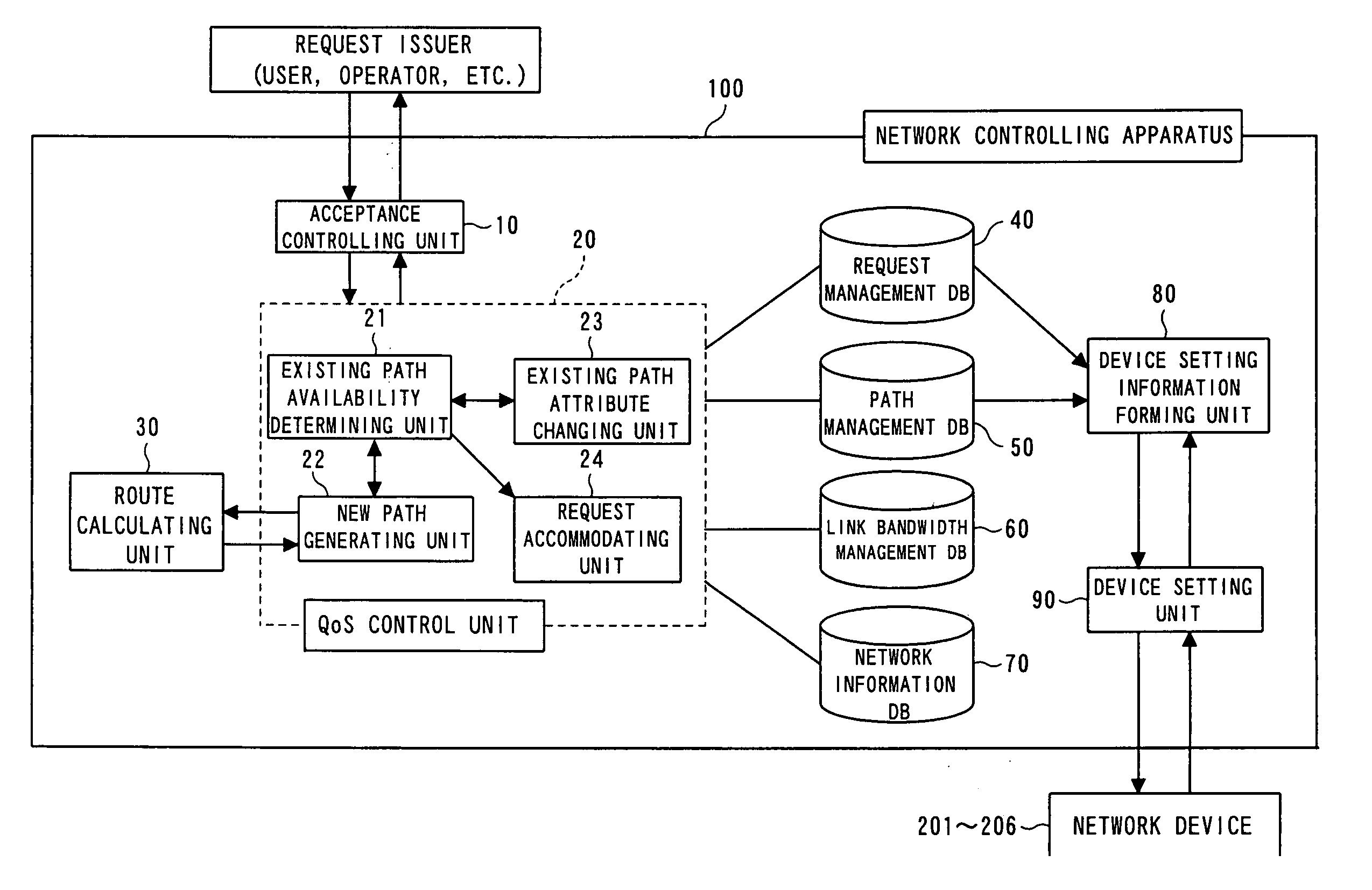
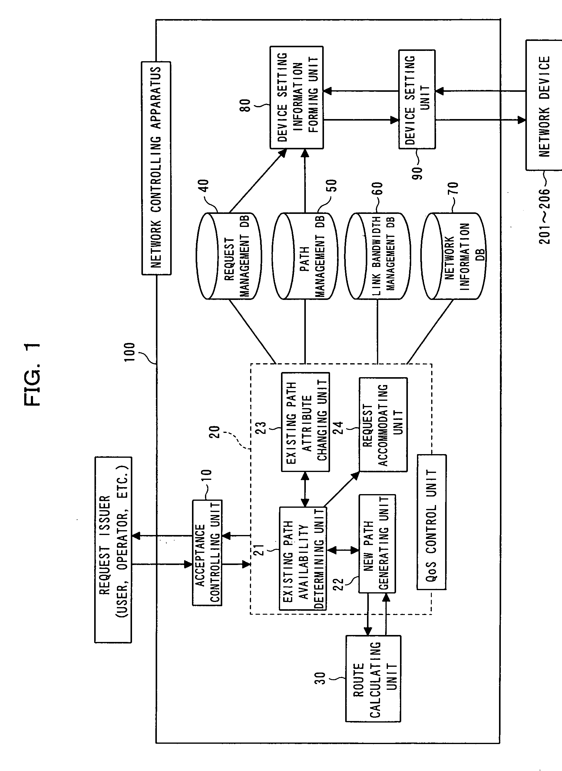
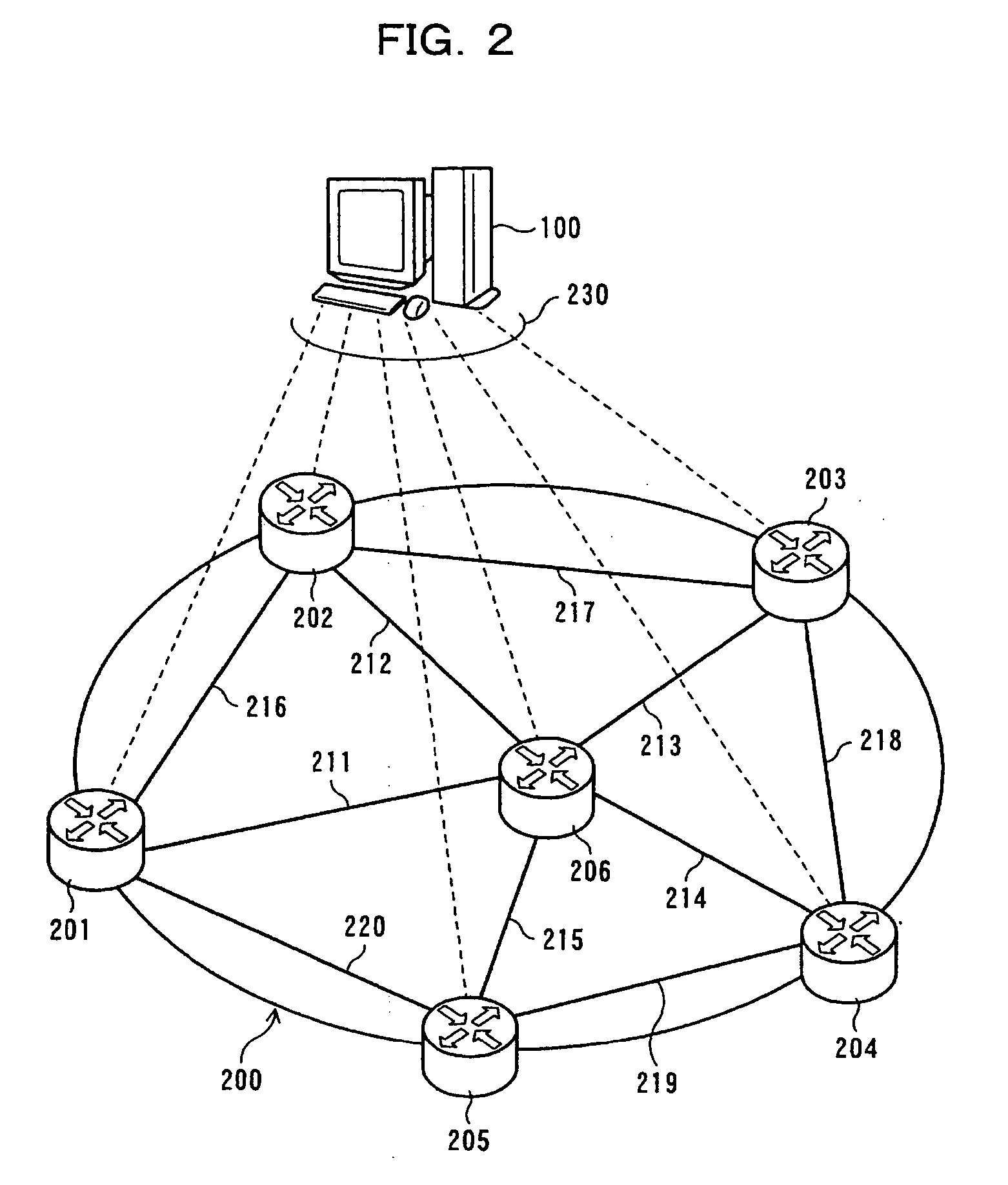
[0057]FIG. 2 is a diagram showing an MPLS network system to which a network controlling apparatus according to an embodiment of this invention is applied. The network controlling apparatus 100 controls setting of the MPLS network 200. The MPLS network 200 is configured by connecting routers 201 through 206, which are a plurality (six in FIG. 2) of network devices, to one another.

[0058] In the MPLS network 200, the routers 201 through 205 are edge routers directly connected to external networks, while the router 206 is a core router not connected to the external network.

[0059] The core router 206 is connected to each of the edge routers 201 through 205 through respective links 211 through 215, and adjacent edge routers 201 through 205 are connected to each other through links 216 through 220.

[0060] In a general IP network, a node determines a node to which an IP p...


PUM


Abstract

A network controlling apparatus appropriately arranges a generated path every hour with a change in section and bandwidth requested in each time period to flexibly generate a path according to the state of occurrence of requests. The network apparatus comprises a storing unit storing information for management of the network, and a controlling unit controlling setting of the network device relating to a connection of network devices at two edge points in the network to obtain path setting satisfying the quality guarantee request, using a path already set or scheduled to be set, or a newly generated path, by referring to the information stored in the storing unit when receiving the quality guarantee request.

Description

BACKGROUND OF THE INVENTION [0001] 1) Field of the Invention [0002] The present invention relates to an apparatus providing a communication service guaranteeing a communication quality in an arbitrary time zone by a reservation in a network, preferably in a label switching network. Particularly, the present invention relates to a network controlling apparatus and a path controlling method in the network controlling apparatus suited to be used when a communication service guaranteeing a communication quality in an arbitrary time zone by a reservation is provided in a network employing MPLS (Multiprotocol Label Switching). [0003] 2) Description of the Related Art [0004] In recent years, research is carried out to provide a bandwidth guaranteed service guaranteeing a communication quality in an arbitrary time zone by a reservation. The bandwidth guaranteed service is a service in which when a user requests a network to provide a communication guaranteeing a bandwidth, the network secur...

Claims


Application Information

Patent Timeline
IPC IPC(8): H04J3/16H04J3/18H04L12/28H04L45/02
CPCH04J3/1694H04L12/5695H04L41/0896H04L41/5003H04L41/5054H04L45/42H04L47/826H04L47/16H04L47/724H04L47/765H04L47/781H04L47/822H04L47/825H04L47/15H04L47/70
Inventor OKAMURA, AKIKOYAMADA, HITOSHI
Owner FUJITSU LTD
Why Eureka
Try Eureka