
Cost-effective multi-channel quadrature amplitude modulation

a quadrature amplitude and multi-channel technology, applied in the field of digital data transmission systems, can solve the problems of high-speed, high-performance processing, data routing, encoding and multiplexing hardware, etc., and achieve the effect of high efficiency and cost-effectiveness

Inactive Publication Date: 2005-08-04
RGB NETWORKS
View PDF8 Cites 35 Cited by
  • Summary
  • Abstract
  • Description
  • Claims
  • Application Information

AI Technical Summary

Problems solved by technology

Clearly, this requires a great deal of high-speed, high-performance processing, data routing, encoding and multiplexing hardware that would not otherwise be required.

Method used


Image

  • Cost-effective multi-channel quadrature amplitude modulation
  • Cost-effective multi-channel quadrature amplitude modulation
  • Cost-effective multi-channel quadrature amplitude modulation

Examples


Embodiment Construction

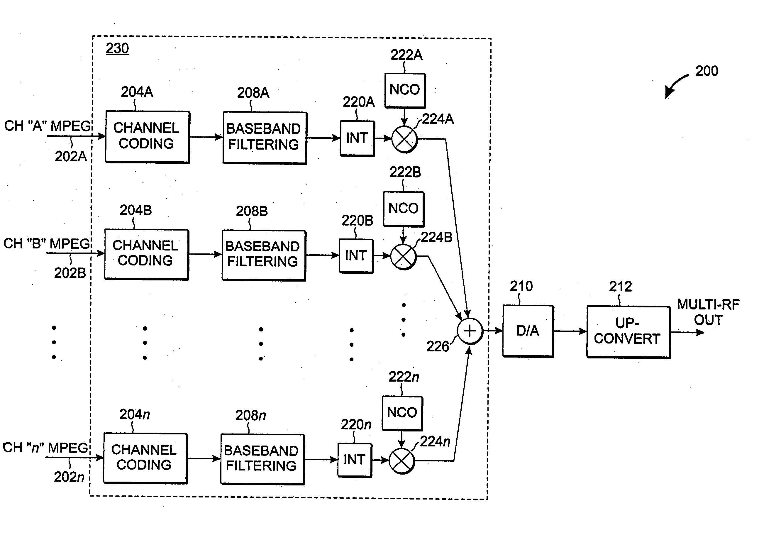
[0029] The present inventive technique provides an efficient, cost-effective means of multiplexing multiple “channels” of digital television and other data onto a single transmission medium.

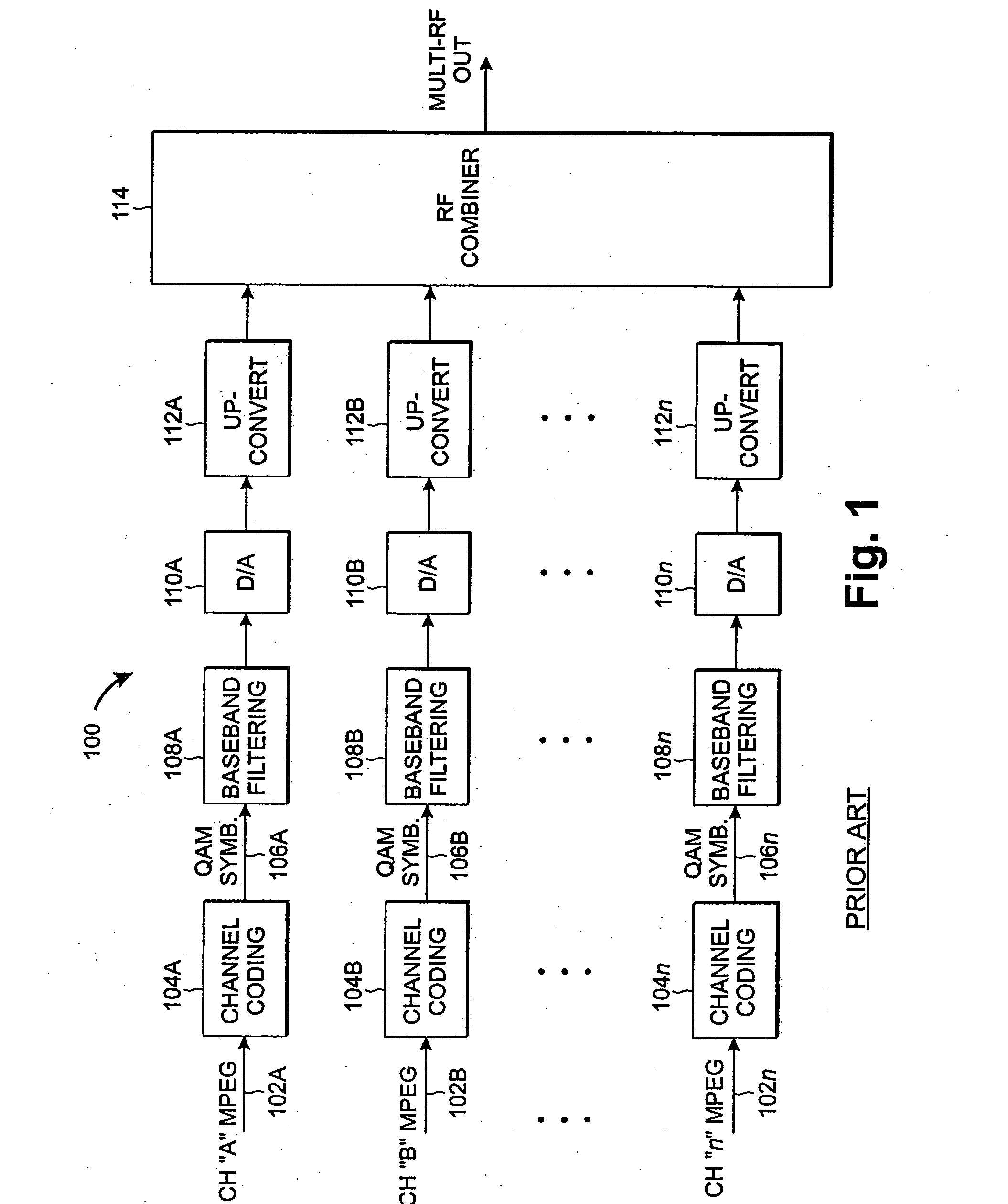
[0030] Most prior-art multi-channel QAM modulators are generally organized as shown in FIG. 1, which shows a system 100 of separate channel modulators being combined (summed) via an RF combiner 114 to produce a multi-channel RF output signal (Multi-RF Out). In FIG. 1, MPEG data streams 102A, 102B, . . . , 102n corresponding to “n” separate program sources are each encoded by a respective channel coder 104A, 104B, . . . , 104n to produce a respective QAM “symbol” stream 106A, 106B, . . . , 106n representing the MPEG data streams 102A, 102B, . . . , 102n. Each QAM symbol stream is encoded according to a suitable standard for digital cable television QAM stream encoding (e.g., ITU-T J.83 Annex A or Annex B, provided by the International Telecommunications Union, Geneva, Switzerland) whereby each QA...


PUM


Abstract

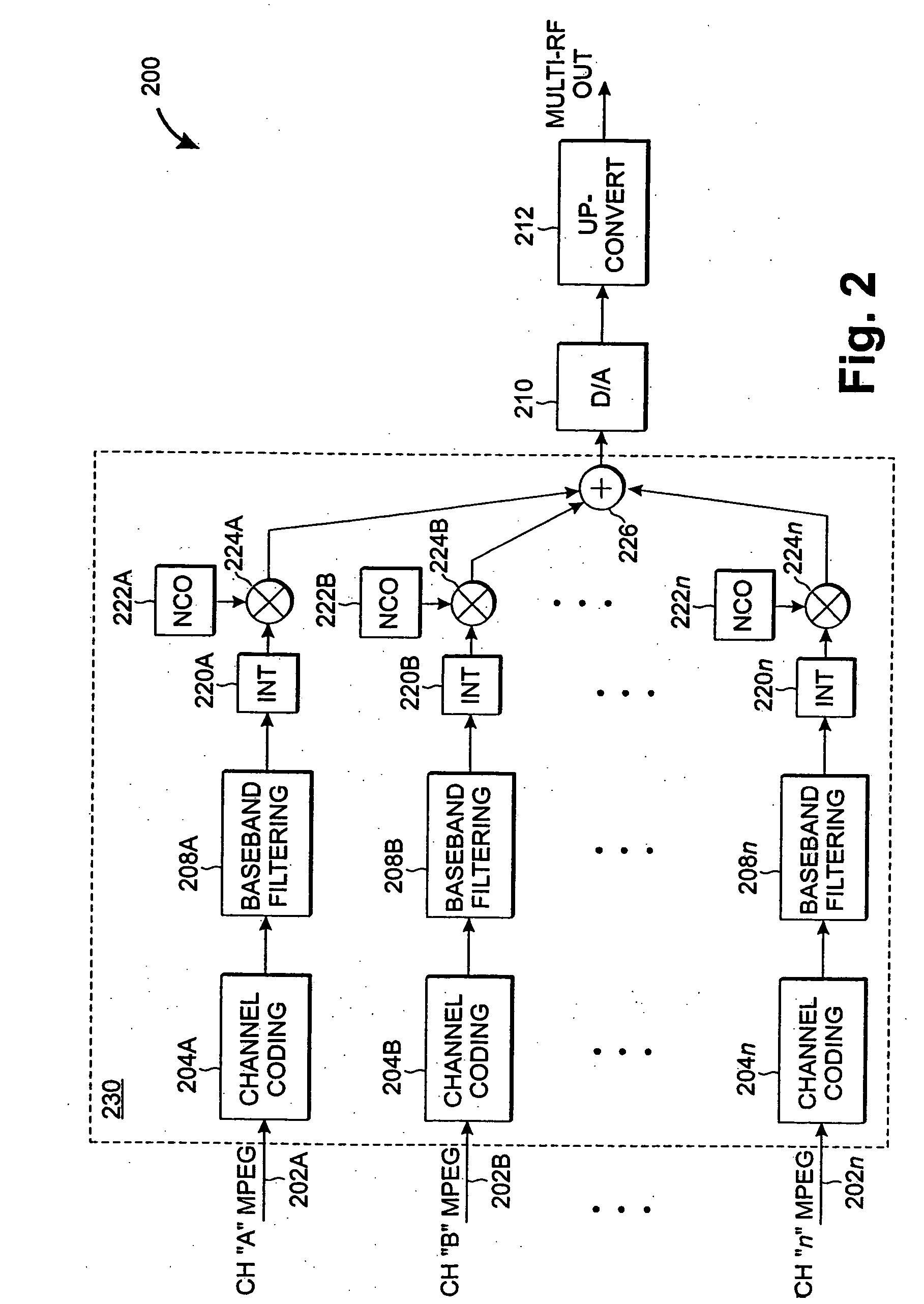
A highly-efficient, cost-effective technique for multi-channel QAM modulation is described. The technique employs an inverse fast-Fourier transform (IFFT) as a multi-channel modulator. QAM encoding expresses QAM symbols as constellation points in the complex plane such that each QAM symbol represents a specific phase and amplitude of a carrier frequency to which it is applied. In multi-channel systems, the carrier frequencies are generally uniformly spaced at a channel-spacing frequency (6 MHz, for digital cable systems in the United States). The IFFT accepts a set of complex frequency inputs, each representing the complex frequency specification (i.e., phase and amplitude) of a particular frequency. The inputs are all uniformly spaced, so assuming that the IFFT is sampled at a rate to provide the appropriate frequency spacing between its frequency-domain inputs, the IFFT will produce a time domain representation of QAM symbols applied to its various inputs modulated onto carriers with the desired channel separation. Since the channel spacing and the symbol rate are different due to excess channel bandwidth, interpolation is used to rectify the difference. An efficient scheme for combining this interpolation with baseband filtering and anti-imaging filtering is described.

Description

CROSS-REFERENCE TO RELATED APPLICATIONS [0001] This application claims the benefit of U.S. Provisional Patent Application No. 60 / 451,336 filed on Feb. 28, 2003 which is incorporated herein by reference. [0002] This application is a continuation of copending application PCT / 2004 / 006064 filed on Mar. 1, 2004, which is incorporated herein by reference. [0003] This application further relates to PCT / U.S. 2004 / 12488 filed on Apr. 21, 2004, which is incorporated herein by reference.TECHNICAL FIELD OF THE INVENTION [0004] The present invention relates to digital data transmission systems, more particularly to multi-channel distribution of digitally-encoded data streams over a cable, optical fiber or similar transmission medium, and still more particularly to multi-channel QAM modulation of digital television data and related data sources. BACKGROUND [0005] Over the last several years, there has been considerable growth in the availability of digital cable and satellite television broadcast...

Claims


Application Information

Patent Timeline
Patent Type & Authority Applications(United States)
IPC IPC(8): H04K1/10H04L27/26
CPCH04L27/2637H04L27/2628H04L27/2634
Inventor MONTA, PETER
Owner RGB NETWORKS
Learn More