Method and apparatus for determining driving lane of vehicle, and computer product

a technology for driving lane and computer products, applied in the direction of image analysis, instruments, computing, etc., can solve the problems of not being able to reliably determine the lane, the driver cannot take turns, and the lanes are impossible to change, so as to achieve the effect of reliably determining the lan

Inactive Publication Date: 2005-08-04
FUJITSU LTD
View PDF17 Cites 50 Cited by
  • Summary
  • Abstract
  • Description
  • Claims
  • Application Information

AI Technical Summary

Benefits of technology

[0009] It is an object of the present invention to provide a technique with which it is possible to reliably determine the lane.

Problems solved by technology

However, sometimes the driver can not take turns in the direction told by the system.
Moreover, while driving straight, sometimes it is impossible to change lanes if there is a lane that is only for cars, or if the own vehicle is near an exit or a branch-off on a freeway.
With the conventional technique it is not reliably possible to determine the lane; because, the road centerline may be a solid line or a broken line, moreover, the lane dividing lines may abruptly change from a solid line to a broken line or vice versa.

Method used


Image

  • Method and apparatus for determining driving lane of vehicle, and computer product
  • Method and apparatus for determining driving lane of vehicle, and computer product
  • Method and apparatus for determining driving lane of vehicle, and computer product

Examples


first embodiment

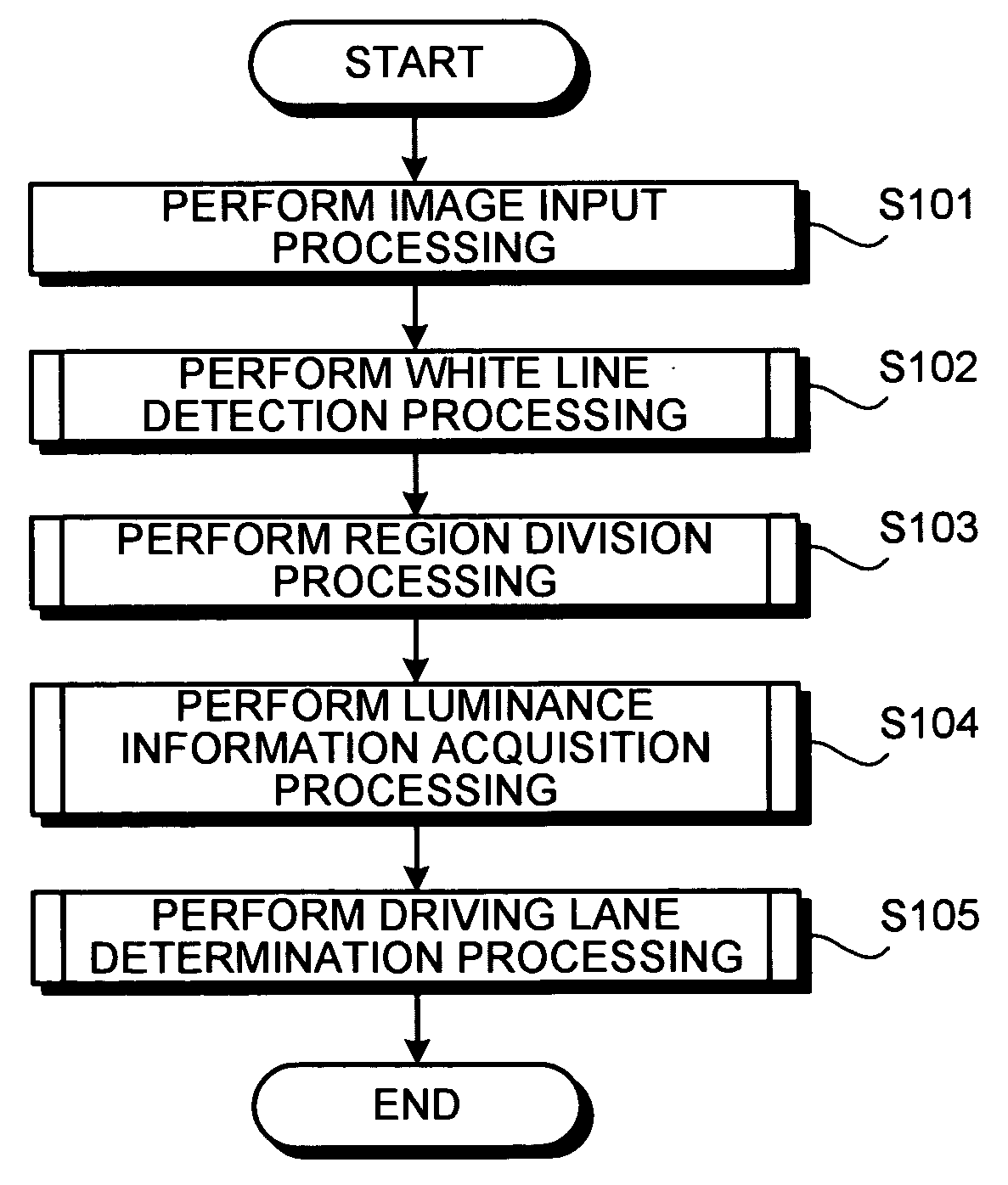
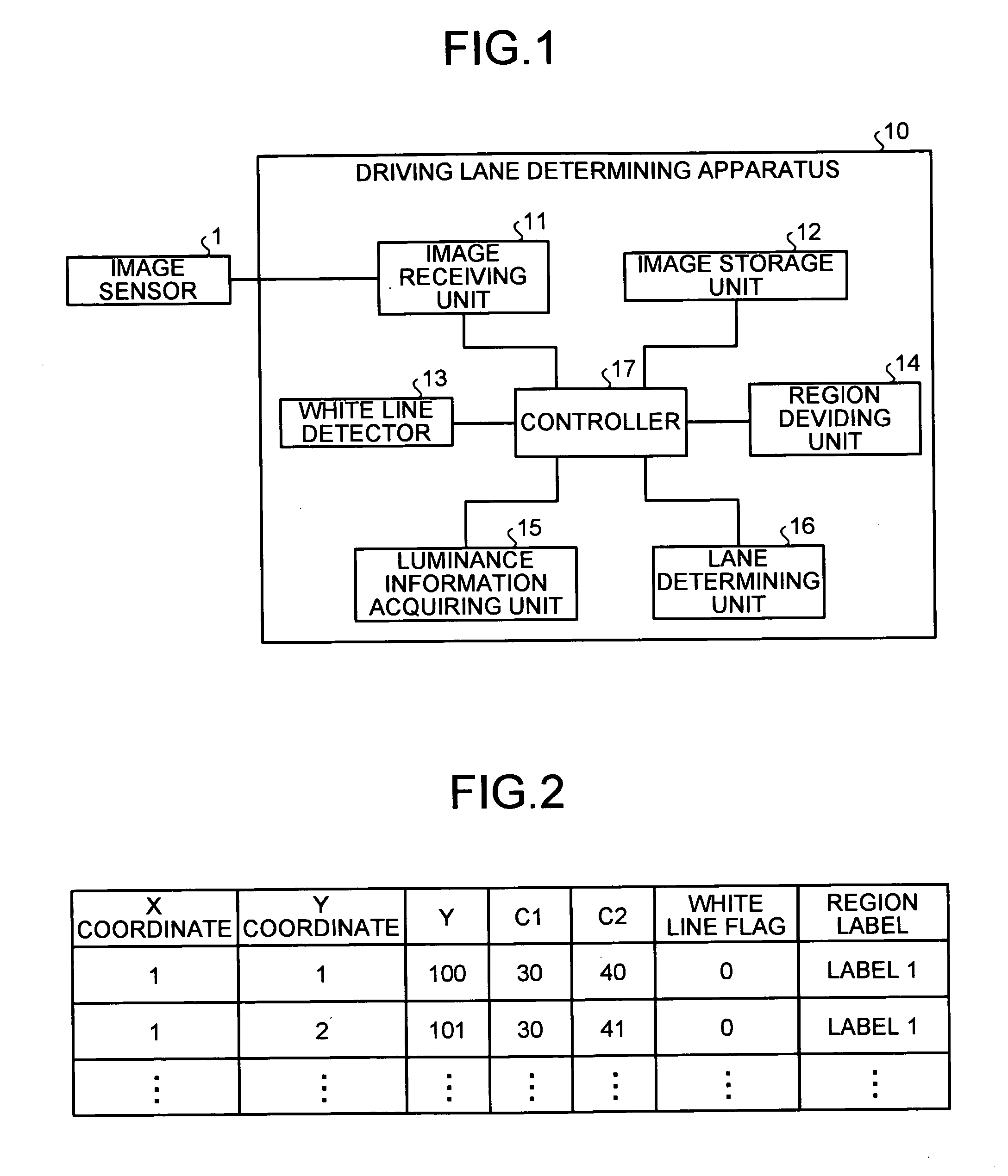
[0073]FIG. 1 is a functional block diagram of a driving lane determining apparatus 10 according to a The driving lane determining apparatus 10 include an image receiving unit 11, an image storage unit 12, a white line detector 13, a region dividing unit 14, a luminance information acquiring unit 15, a lane determining unit 16, and a controller 17.

[0074] An image sensor 1 is installed in front of a own vehicle in such a manner that lane lines on two sides of the own vehicle can be captured. The image captured by the image sensor 1 is input into the image receiving unit 11. The image receiving unit 11 stores the image in the image storage unit 12.

[0075] This embodiment assumes that an image sensor installed on the front of the own vehicle captures an image of the lane lines on two sides of the own vehicle. However, one image sensor may be installed on each side of the own vehicle to capture an image of corresponding lane line.

[0076] The image sensor 1 may be black-and-white or colo...

second embodiment

[0127]FIG. 11 is a functional block diagram of a driving lane determining apparatus 20 according to the For convenience, the functional units performing like roles as those of the respective units shown in FIG. 1 are designated by like reference signs, and the detailed explanation thereof is omitted.

[0128] The driving lane determining apparatus 20 includes the image receiving unit 11, the image storage unit 12, the white line detector 13, the region dividing unit 14, a color information acquiring unit 25, a lane determining unit 26, and a controller 27 that controls the whole driving lane determining apparatus 20.

[0129] The color information acquiring unit 25 calculates a mean value of color differences (C1, C2) between respective regions in the image divided by the region dividing unit 14. Since the road surface is generally monotonous, the color saturation is low. On the other hand, portions other than the road surface are not monotonous, and may have high color saturation. The ...

third embodiment

[0140]FIG. 13 is a functional block diagram of a driving lane determining apparatus 30 according to the For convenience, the functional units performing like roles as those of the respective units shown in FIG. 1 or FIG. 11 are designated by like reference signs, and the detailed explanation thereof is omitted.

[0141] The driving lane determining apparatus 30 includes the image receiving unit 11, the image storage unit 12, the white line detector 13, the region dividing unit 14, the luminance information acquiring unit 15, the color information acquiring unit 25, the lane determining unit 36, and a controller 37 that controls the whole driving lane determining apparatus 30.

[0142] In other words, the driving lane determining apparatus 30 has both the luminance information acquiring unit 15 that calculates a luminance mean value in each region divided into three by the region dividing unit 14, and the color information acquiring unit 25 that calculates a mean value of the color diffe...


PUM


Abstract

A white line detector detects two white lines from predetermined regions of an image, and a region dividing unit uses the two white lines detected by the white line detector to divide the image into multiple regions. A luminance information acquiring unit calculates the luminance mean value of the respective regions divided into three by the region dividing unit, and the lane determining unit determines the driving lane by using the luminance mean value calculated by the luminance information acquiring unit.

Description

BACKGROUND OF THE INVENTION [0001] 1) Field of the Invention [0002] The present invention relates to a technology for determining the driving lane of a vehicle. [0003] 2) Description of the Related Art [0004] Car navigation systems those obtain and display a driving route between a current position and a destination of the vehicle have appeared in the market. These car navigation systems employ a digital map and the global positioning system (GPS) to decide the positions of the vehicles. [0005] A car navigation system calculates the position of the vehicle (hereinafter, “own vehicle”), in which it is installed, based on the position data of the own vehicle obtained from the GPS, and displays the position on a digital map. The car navigation system can also vocally and / or visually inform the driving route to the driver of the own vehicle. [0006] Moreover, the car navigation systems can tell the drivers to turn left or to turn right at an intersection. However, sometimes the driver ca...

Claims


Application Information

Patent Timeline
Patent Type & Authority Applications(United States)
IPC IPC(8): G06T7/40G06T1/00G06V10/48G08G1/16
CPCG06K9/4633G06K9/00798G06V20/588G06V10/48
Inventor FUJII, ASAKOTAKASHIMA, TOMONOBU
Owner FUJITSU LTD
Why Eureka
Try Eureka