Fluid bearing device
a technology of fluid bearings and bearings, which is applied in the direction of bearings, shafts and bearings, rotary bearings, etc., can solve the problems of increasing torque loss and inability to obtain desired performance, and achieve good wear resistance of bearings, accurate hydrodynamic bearings, and good workability of sleeves and grooves for dynamic pressure generation.
- Summary
- Abstract
- Description
- Claims
- Application Information
AI Technical Summary
Benefits of technology
Problems solved by technology
Method used
Image
Examples
first embodiment
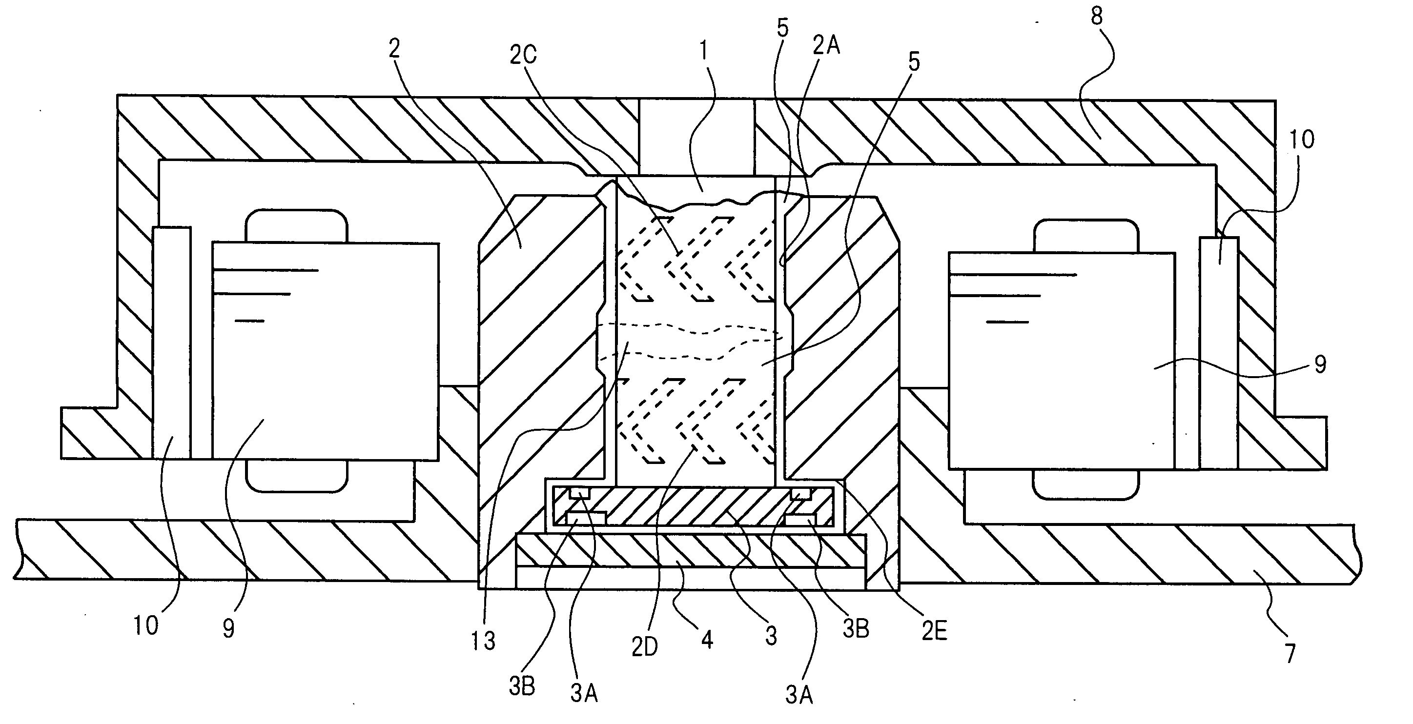
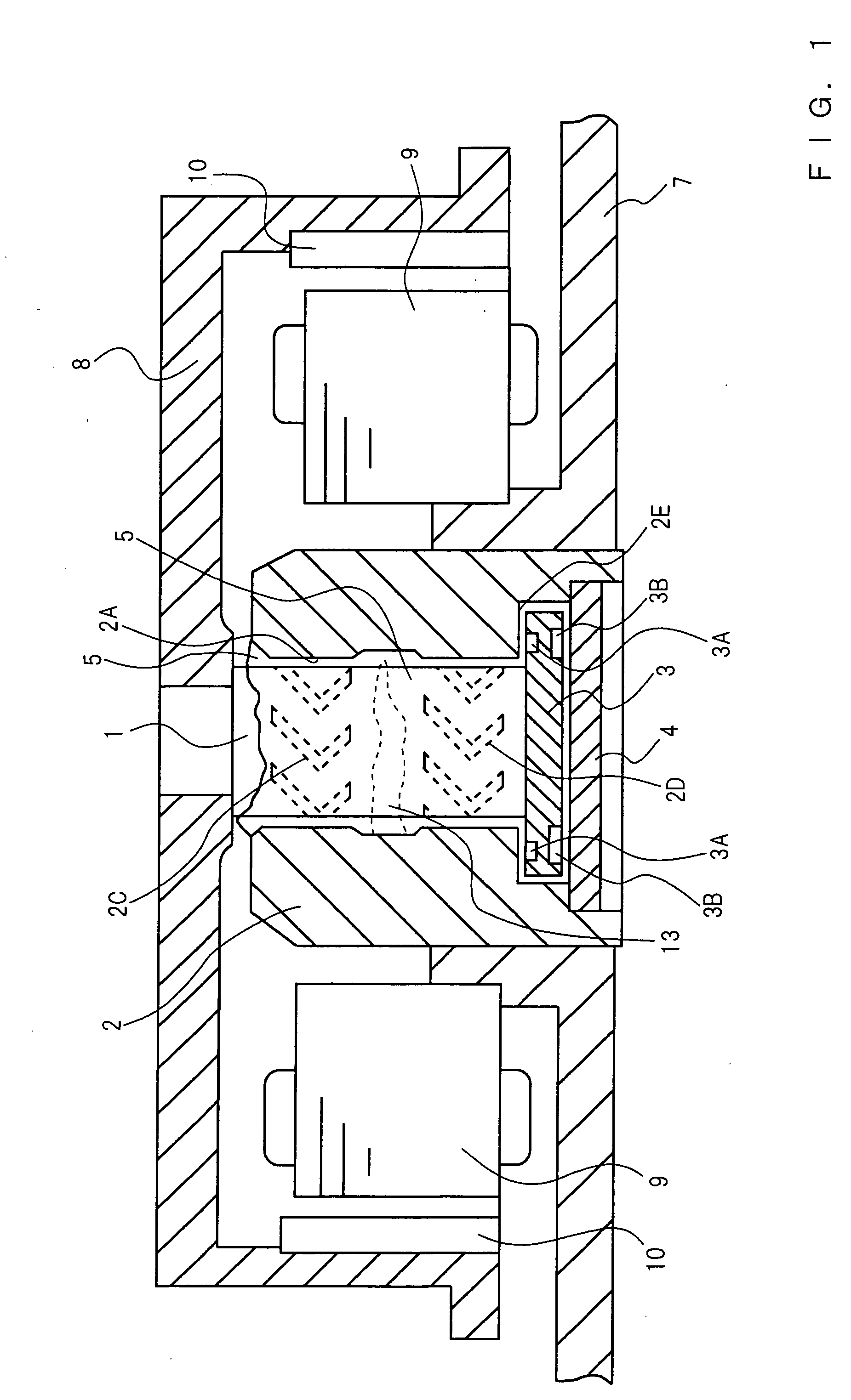
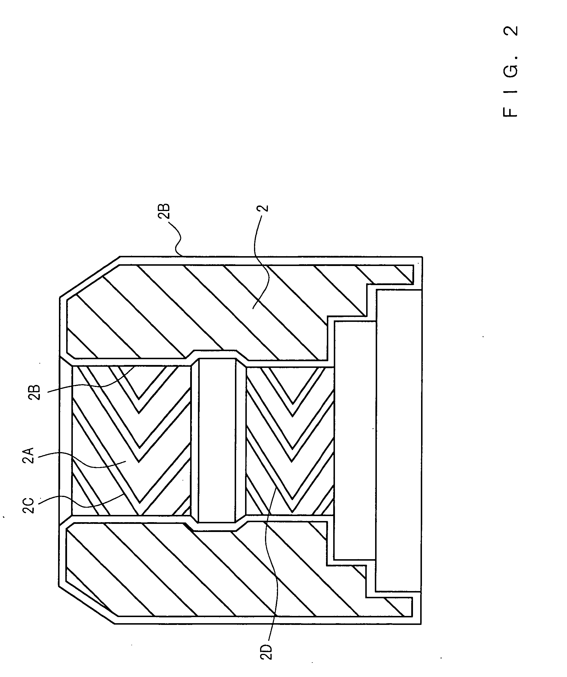
[0038] A hydrodynamic bearing in accordance with a first embodiment of the present invention will be described referring to FIGS. 1 to 9. FIG. 1 is a cross-sectional view of the hydrodynamic bearing in accordance with the first embodiment of the present invention, and FIG. 2 is a magnified cross-sectional view of a sleeve 2. In FIG. 1, the sleeve 2 has a bearing hole 2A, and a shaft 1 is rotatably inserted into this bearing hole 2A. Dynamic pressure generation grooves 2C and 2D which are configured by herringbone-pattern-shaped shallow grooves are formed on at least one of the outer circumferential face of the shaft 1 and the inner circumferential face of the bearing hole 2A of the sleeve 2, whereby a radial bearing portion is formed. In the example shown in FIG. 1, the dynamic pressure generation grooves 2C and 2D are formed on the inner circumferential face of the bearing hole 2A. Both the dynamic pressure generation grooves 2C and 2D are fishbone-shaped (herringbone-shaped); in F...
second embodiment
[0052] A hydrodynamic bearing in accordance with a second embodiment of the present invention will be described referring to FIGS. 10 to 13. FIG. 10 is a cross-sectional view of the hydrodynamic bearing in accordance with the second embodiment of the present invention. In the figure, a shaft 101 is rotatably inserted into the bearing hole 102A of a sleeve 102. As shown in FIG. 13 of a magnified cross-sectional view of the main portion, between the main body 101D and the small-diameter portion 101E of the shaft 101, a groove 101A is formed around the small-diameter portion 101E. The groove 101A is deepest at the small-diameter portion 101E and gradually becomes shallower toward the outer circumferential portion of the main body 101D.
[0053] In FIG. 10, a ring-shaped retainer 103 is mounted on the upper end of the sleeve 102 to prevent the shaft 101 from coming off from the sleeve 102. The inside diameter of the retainer 103 is set so as to cover about a half of the above-mentioned gr...
PUM
| Property | Measurement | Unit |
|---|---|---|
| diameter | aaaaa | aaaaa |
| diameter | aaaaa | aaaaa |
| thickness | aaaaa | aaaaa |
Abstract
Description
Claims
Application Information
 - R&D
- Intellectual Property
- Life Sciences
- Materials
- Tech Scout
- Unparalleled Data Quality
- Higher Quality Content
- 60% Fewer Hallucinations
Browse by: Latest US Patents, China's latest patents, Technical Efficacy Thesaurus, Application Domain, Technology Topic, Popular Technical Reports.
© 2025 PatSnap. All rights reserved.Legal|Privacy policy|Modern Slavery Act Transparency Statement|Sitemap|About US| Contact US: help@patsnap.com


