
Tool coolant application and direction assembly

Inactive Publication Date: 2005-08-04
ADVANCED NT
View PDF28 Cites 42 Cited by
  • Summary
  • Abstract
  • Description
  • Claims
  • Application Information

AI Technical Summary

Benefits of technology

[0008] The insert also includes at least one coolant hole communicating coolant fluid to an interface between the rotating tool and an inner diameter of the insert. The coolant hole creates a fluid bearing between the tool and the inner diameter of the insert that retards frictional build-up of heat. The inner diameter of the insert slides over the rotating tool and is held in place on the tool by a semi-flexible coolant line. The collar simply slides over the rotating tool providing for quick tooling changeovers.
[0011] Accordingly, embodiments of this invention provide easy mounting to existing tooling and machinery while directs coolant along the entire length of a tool without complex piping and valving and does not interfere with the work piece tool interface during machining.

Problems solved by technology

Without coolant flow, friction from the tool and the workpiece generate heat of a degree sufficient to damage the tool.
Further, not only would the tool be damaged, but also the quality of the machines surface of the work piece is degraded.
Often during the machining, the work piece or chips bump and contact the coolant lines changing the position of the hose such that the coolant is no longer directed as originally positioned onto the tool.
In addition, hoses are often not positionable for providing coolant as desired when machining of relatively deep openings or holes.
Further, in some part configurations an adjustable coolant hose is simply not feasible and does not supply and direct coolant flow adequately to the tool.
Such systems require expensive and complicated fluid routing mechanisms in order to route coolant fluid substantially near the axis of rotation of the tool.
Further, such systems are not easily adaptable to tool changes.

Method used


Image

  • Tool coolant application and direction assembly
  • Tool coolant application and direction assembly
  • Tool coolant application and direction assembly

Examples


Embodiment Construction

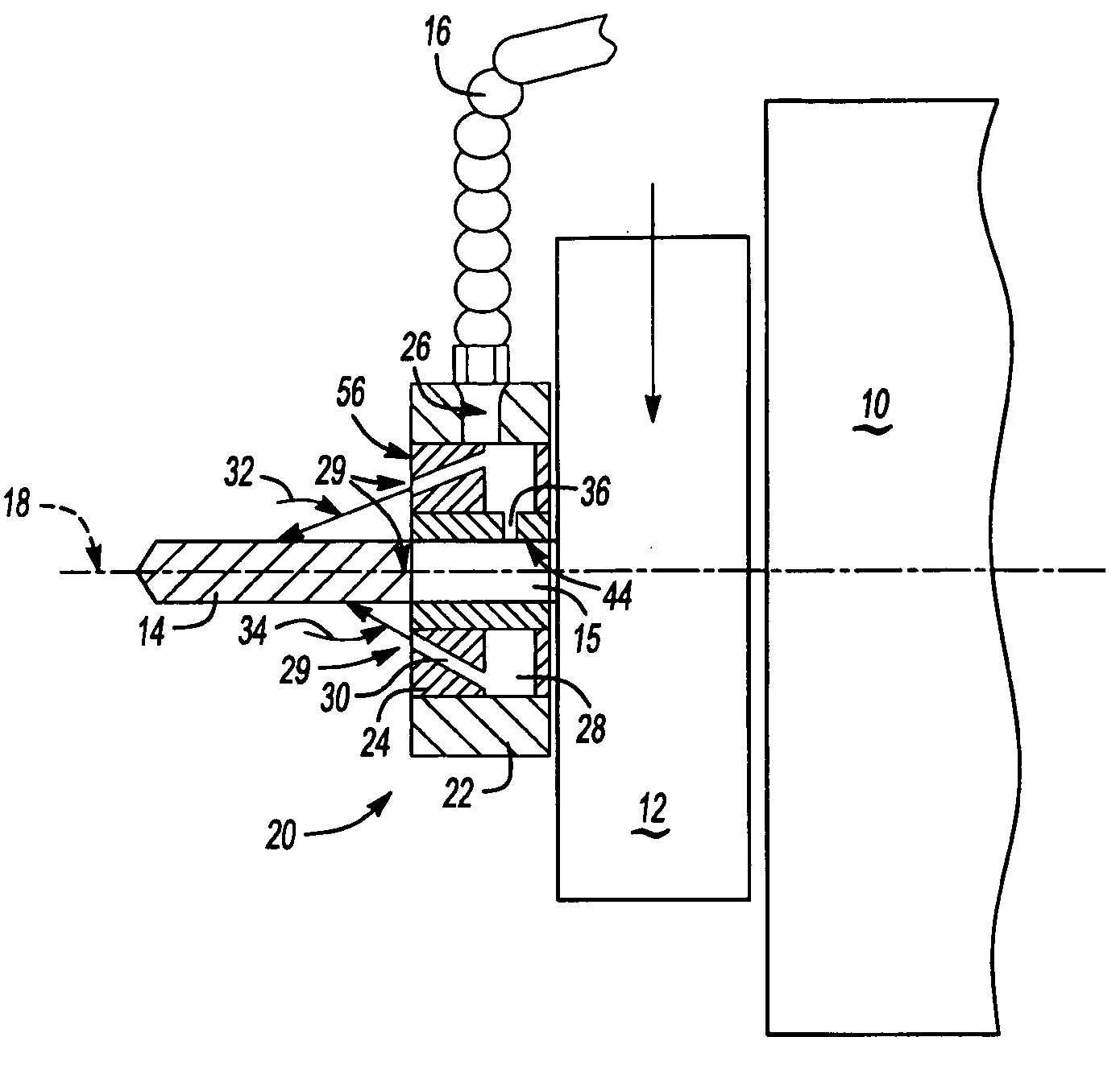
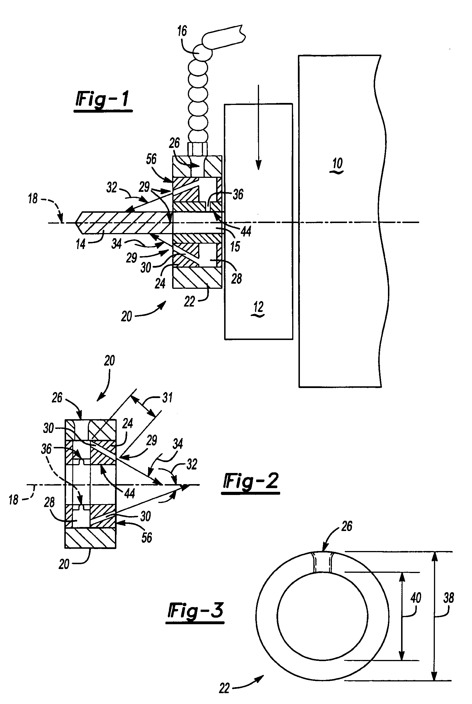
[0036] Referring to the FIG. 1, a machine 10 rotates a spindle 12 and tool 14 about an axis 18. The tool 14 is of any kind known to a worker skilled in the art. Disposed about the tool 14 is a coolant collar assembly 20. The coolant collar 20 is held in place by semi-rigid coolant line 16. The coolant line 16 is a hose or pipe capable of maintaining a desired position as understood by a worker skilled in the art. The collar 20 slides over the tool 14 and abuts the spindle 12. The coolant collar 20 includes an outer ring 22 having a coolant inlet 26. Within the outer ring 22 is insert 24. The insert 24 includes an annular channel 28 in fluid communication with the inlet 26 of the outer ring 22 to provide fluid to coolant passages 30. The coolant passages 30 are disposed at an angle relative to the axis of rotation 18 to direct coolant flow along the tool 14.

[0037] Each of the passages 30 terminates at an opening 29 on the face 56 of the insert. No portion of the passage 30 extends p...


PUM

PropertyMeasurementUnit
Angleaaaaaaaaaa
Angleaaaaaaaaaa
Lengthaaaaaaaaaa

Abstract

A coolant assembly for supplying coolant fluid to a tool includes an outer ring defining an inlet and an insert pressed within the outer ring including an annular channel. The annular channel is in communication with the inlet defined by the outer ring and includes a plurality of passages disposed to direct fluid along an axis of a tool. At least two of the passages are disposed at different angles relative to the axis of the tool to direct coolant along the entire length of the tool in order to provide a uniform and consistent stream of coolant and uniform and consistent temperature of the tool.

Description

REFERENCE TO RELATED APPLICATION This application is a continuation of co-pending U.S. patent application Ser. No. 10 / 197,390 filed on Jul. 17, 2002.BACKGROUND OF THE INVENTION [0001] This invention relates to an assembly for directing coolant flow onto a machine tool, and specifically to an assembly for directing coolant flow onto a tool at different locations along the rotational axis. [0002] Typically, in a conventional machining process a stream of coolant is directed onto the cutting tool to maintain a constant temperature. Without coolant flow, friction from the tool and the workpiece generate heat of a degree sufficient to damage the tool. Further, not only would the tool be damaged, but also the quality of the machines surface of the work piece is degraded. For these reasons it is desirable direct a stream of coolant onto a tool during machining operations. Machining produces metal chips that are preferably evacuated from the machining area in order to prevent damage to the ...

Claims


Application Information

Patent Timeline
IPC IPC(8): B23Q1/00B23Q11/10
CPCB23Q1/0036B23Q11/1076Y10T279/17111Y10T408/44Y10T408/46Y10T409/304032
Inventor BECKINGTON, KEVIN
Owner ADVANCED NT
Learn More