Method and apparatus for purging seals in a thermal reactor

a technology of thermal reactor and seal, applied in the direction of cleaning process and apparatus, light and heating apparatus, furnace components, etc., can solve the problems of non-hermetic seal, undesirable complications, non-uniform processing,

Active Publication Date: 2005-08-04
ASM INTERNATIONAL
View PDF11 Cites 131 Cited by
  • Summary
  • Abstract
  • Description
  • Claims
  • Application Information

AI Technical Summary

Benefits of technology

[0008] Thus, in accordance with one aspect of the invention, a mechanical seal at a downstream end of a thermal reactor is purged with a purging gas, wherein the selection of the purging gas depends on the density of the process gas and the position of the seal. When the seal is positioned at a lower end of the reactor, a purging gas is selected that is heavier than the process gas used. When the seal is positioned at an upper end of the reactor, a purging gas is selected that is lighter than the process gas used. Preferably, a gas exhaust is located at about the same end of the reactor as the seal. By “heavier,” it is meant that the purge gas has a molecurar weight that is greater than the molecular weight of the process gas. Conversely, by “lighter,” the reverse is meant; that is, the purge gas has a molecular weight that is smaller than the molecular weight of the process gas.

Problems solved by technology

While these mechanical seals are preferably gas-tight to minimize process degradation due to interactions with the ambient environment, some of these seals may not be hermetic due to the high temperatures that are locally present at and around the seals.
It has been found, however, that this purging of the seal can itself cause undesirable complications.
Moreover, this dilution might not be uniform over the entire volume of the reaction chamber, resulting in non-uniformities in processing results which vary depending upon location within the reaction chamber.
For example, non-uniform thermal oxide films can arise when inert gas is used to purge the rotational feed-through of a boat rotation mechanism for a reaction chamber that is part of a vertical furnace.

Method used


Image

  • Method and apparatus for purging seals in a thermal reactor
  • Method and apparatus for purging seals in a thermal reactor
  • Method and apparatus for purging seals in a thermal reactor

Examples


Embodiment Construction

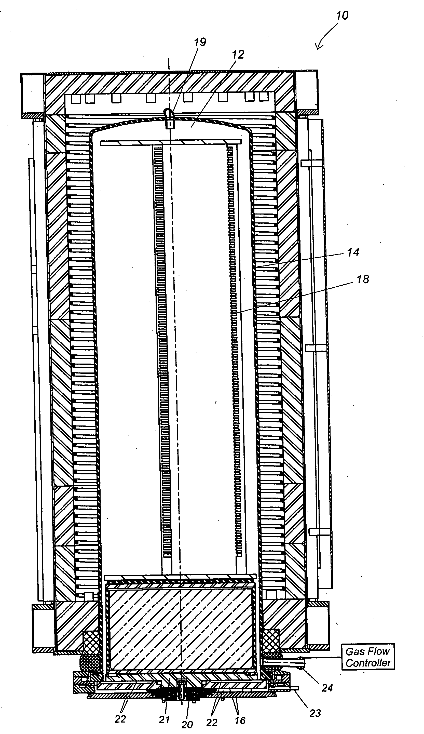
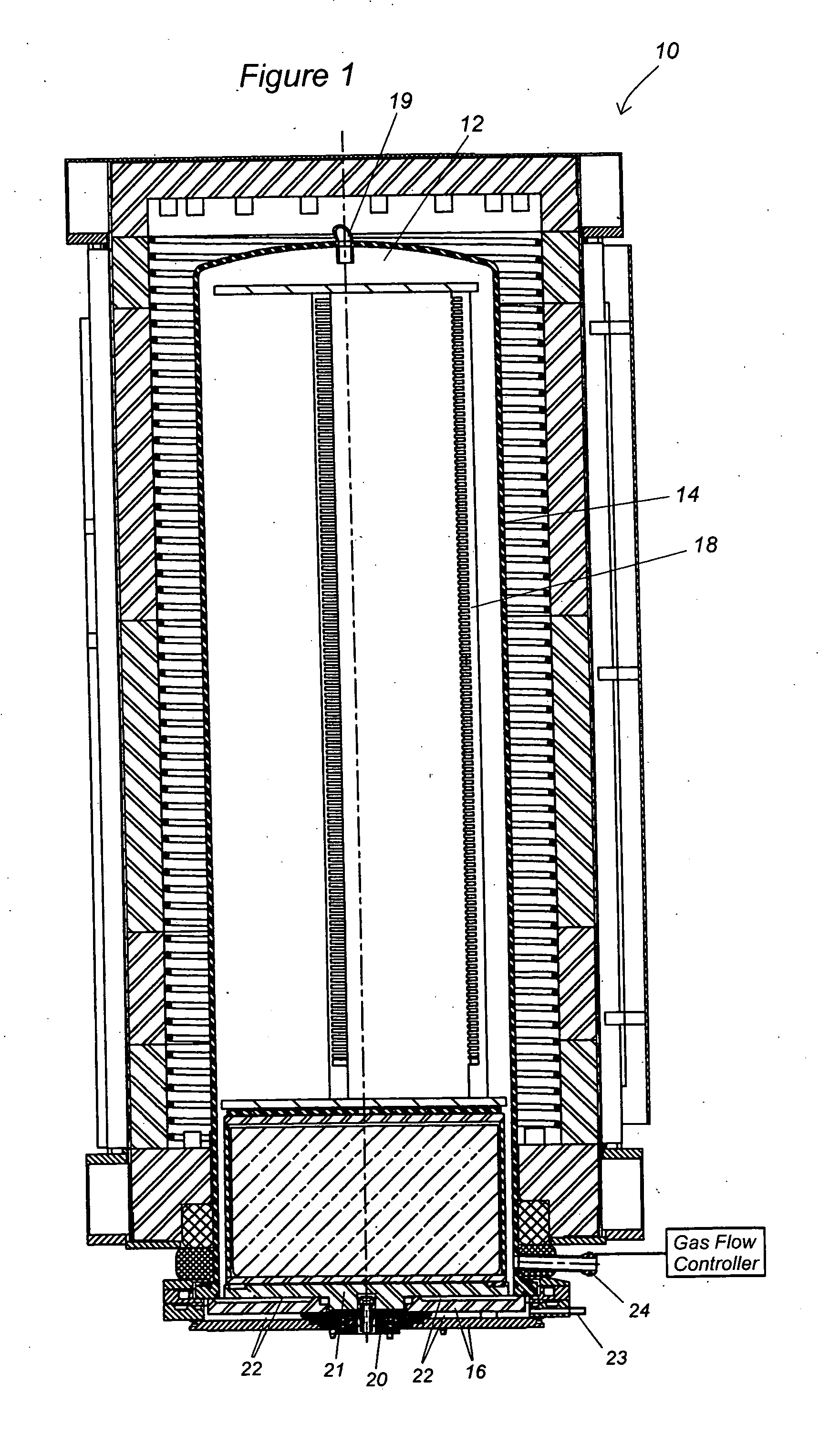
[0016] While the invention has application to various reactors known in the art, it is particularly advantageous when applied to reactors that are vertical furnaces. An exemplary reactor 10 is shown in FIG. 1 and is available commercially under the trade name A412™ from ASM International, N.V. of The Netherlands. The reaction chamber 12 is delimited by a substantially cylindrical process tube 14 extending in a vertical direction. The lower side of the tube is open and can be closed with a door 16. The door 16 supports a boat 18 that accommodates a plurality of substrates, such as wafers (not shown), in a vertically stacked manner. Process gas enters the reaction chamber 12 via the process gas inlet 19 proximate the top of the reaction chamber 12 and typically flows downward to exit the reaction chamber 12 via the gas exhaust 24 proximate the bottom of the reaction chamber 12.

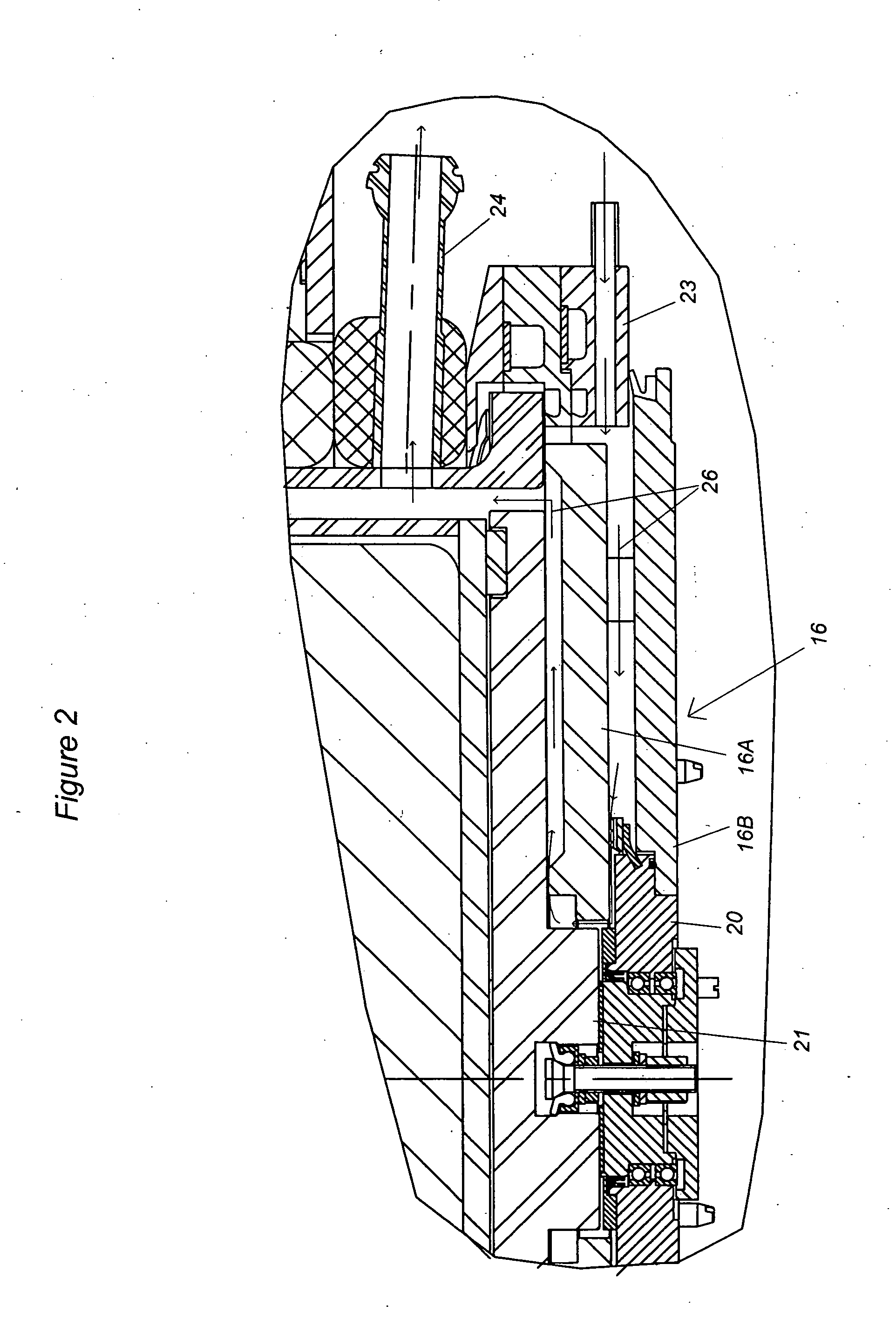
[0017] In the illustrated embodiment, the door 16 is provided with a boat rotation bearing 20 that is config...


PUM


Abstract

A semiconductor processing reactor comprises a reaction chamber with a gas exhaust and a mechanical seal at one end of the chamber. The seal seals off the chamber from the ambient environment and is purged with gas to prevent diffusion of ambient gases into the reaction chamber. Because the purge gas can diffuse through the seal into the reaction chamber, the purge gas is chosen based upon the process gas and the location of the seal and exhaust so that the molecular weight of the purge gas causes the purge gas, by the force of gravity or buoyancy, to remain in the portion of the reaction chamber containing the seal and the gas exhaust. Advantageously, keeping the purge gas at the same end of the chamber as the gas exhaust minimizes dilution of the process gas with the purge gas, thereby preventing the purge gas from detrimentally effecting process results.

Description

REFERENCE TO RELATED APPLICATION [0001] This application claims the priority benefit under 35 U.S.C. §119(e) of provisional Application No. 60 / 538,351, filed Jan. 21, 2004. The application is also related to U.S. Pat. No. 6,746,240, PROCESS TUBE SUPPORT SLEEVE WITH CIRCUMFERENTIAL CHANNELS, issued Jun. 8, 2004, the entire disclosure of which is incorporated herein by reference.FIELD OF THE INVENTION [0002] This invention relates generally to the field of semiconductor processing and, more particularly, to thermal reactors used for thermal processing. BACKGROUND AND SUMMARY OF THE INVENTION [0003] A thermal reactor typically comprises a reaction chamber which is sealed from the chamber's ambient environment. The reaction chamber might comprise mechanical seals at some places, e.g., at the position of an openable door which allows feeding one or more substrates into the reaction chamber, or at a position where a gas feed tube or gas exhaust tube is connected to the chamber. In chamber...

Claims


Application Information

Patent Timeline
Patent Type & Authority Applications(United States)
IPC IPC(8): H01L21/31B08B5/00B08B7/00G01M3/04H01L21/00
CPCH01L21/67126B08B5/00B08B7/00
Inventor MARIA OOSTERLAKEN, THEODORUS GERARDUSHUUSSEN, FRANKTERHORST, HERBERTVAN PUTTEN, JACK H.
Owner ASM INTERNATIONAL
Why Eureka
Try Eureka