Spacer for delivery of medications from an inhaler to children and breathing impaired patients

a spacer and inhaler technology, applied in the field of spacers for delivering medications from inhalers to children and breathing impaired patients, can solve the problems of affecting particle size, affecting particle size, and affecting particle size, so as to reduce the formation of adverse recirculation zones and improve the effect of medication supply

Active Publication Date: 2005-08-11
CFD RES CORP
View PDF57 Cites 10 Cited by
  • Summary
  • Abstract
  • Description
  • Claims
  • Application Information

AI Technical Summary

Benefits of technology

[0012] The design of the spacer of the present invention effectively channels the spray down the centerline of the spacer and limits contact between medication particles and the walls of the spacer (deposition). Further, the spacer of this invention minimizes the formation of any adverse recirculation zones that trap medication particles within the spacer. Rather, by a careful and novel design, the present invention creates and takes advantage of high-pressure recirculation zones that tend to force the medication spray away from the walls of the spacer and into a preferred, central spray pattern. Consequently, the spacer of the present invention delivers a higher percentage of the medication to the deep lung regions of the patient.
[0013] To accomplish this, one embodiment of the spacer of the present invention includes a first conical body joined to a second conical body, forming a continuous spray conduit through first and second internal chambers of the respective first and second conical bodies. A mouthpiece is formed in the small diameter (proximal, downstream) end of the first conical body. A spray inlet for attachment to an MDI or similar device is formed at the large diameter (distal, upstream) end of the second conical body. A plurality of air inlets are placed downstream of the medication inlet proximate to, or in, the large diameter distal end surface of the first conical body. During use, high-pressure air recirculation zones are created in the first and second chambers, near the spray inlet and the air inlets, and an air jacket is created along the inner surface of the wall of the first conical body. This forces the medication spray through the spacer into a defined airflow path through the spray conduit, minimizing particle entrapment and contact with the walls of the spacer.

Problems solved by technology

Unfortunately, in conventional spacers, as much as 50% of the medication is lost before delivery to the patient because of inefficient design of the spacer itself.
Also, while it is known that medication particles having a diameter in the range of 3-5 microns are desirable for delivery to deep lung tissue, conventional spacers do a poor job of consistently delivering particles of this size.
This is because existing spacer designs do not effectively control the heat exchange rate and the length of time that the medication particles remain inside the spacer, factors which directly affect particle size.
Finally, prior art spacers typically include air inlets at the upstream (spray discharge) end near the mouthpiece but they cannot maintain consistent flow energy.
All of these factors will cause undesirable deposition of the medication droplets in the oro-pharyngeal region of the patient.
The inefficient delivery of medication to the deep lung results in either under-medication of the patient or the waste of expensive medications.

Method used


Image

  • Spacer for delivery of medications from an inhaler to children and breathing impaired patients
  • Spacer for delivery of medications from an inhaler to children and breathing impaired patients
  • Spacer for delivery of medications from an inhaler to children and breathing impaired patients

Examples


Embodiment Construction

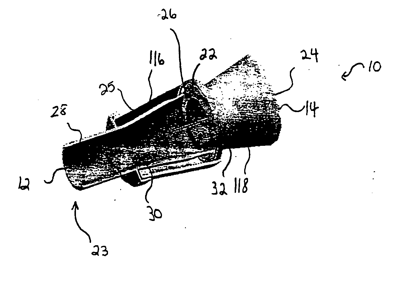
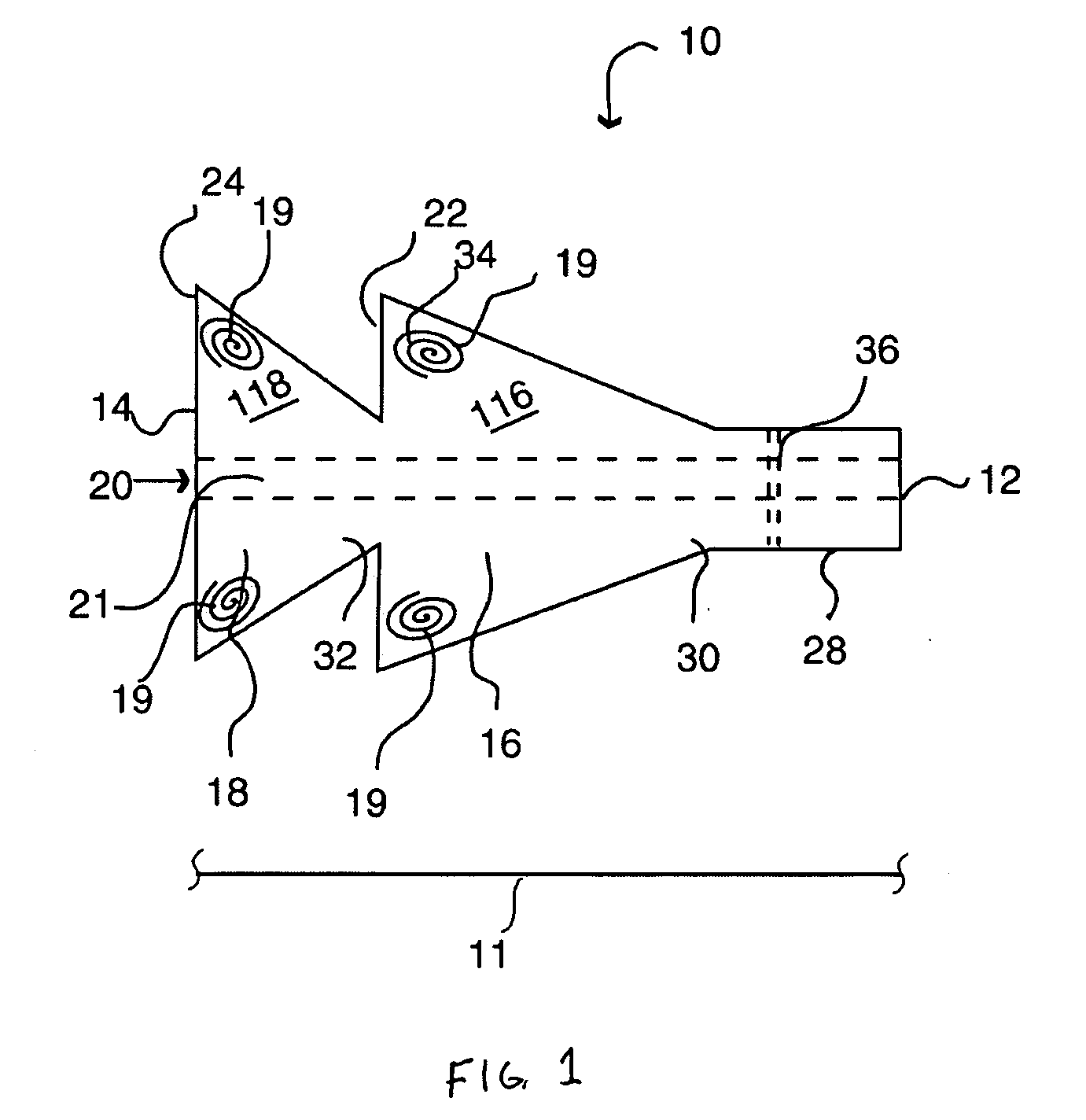
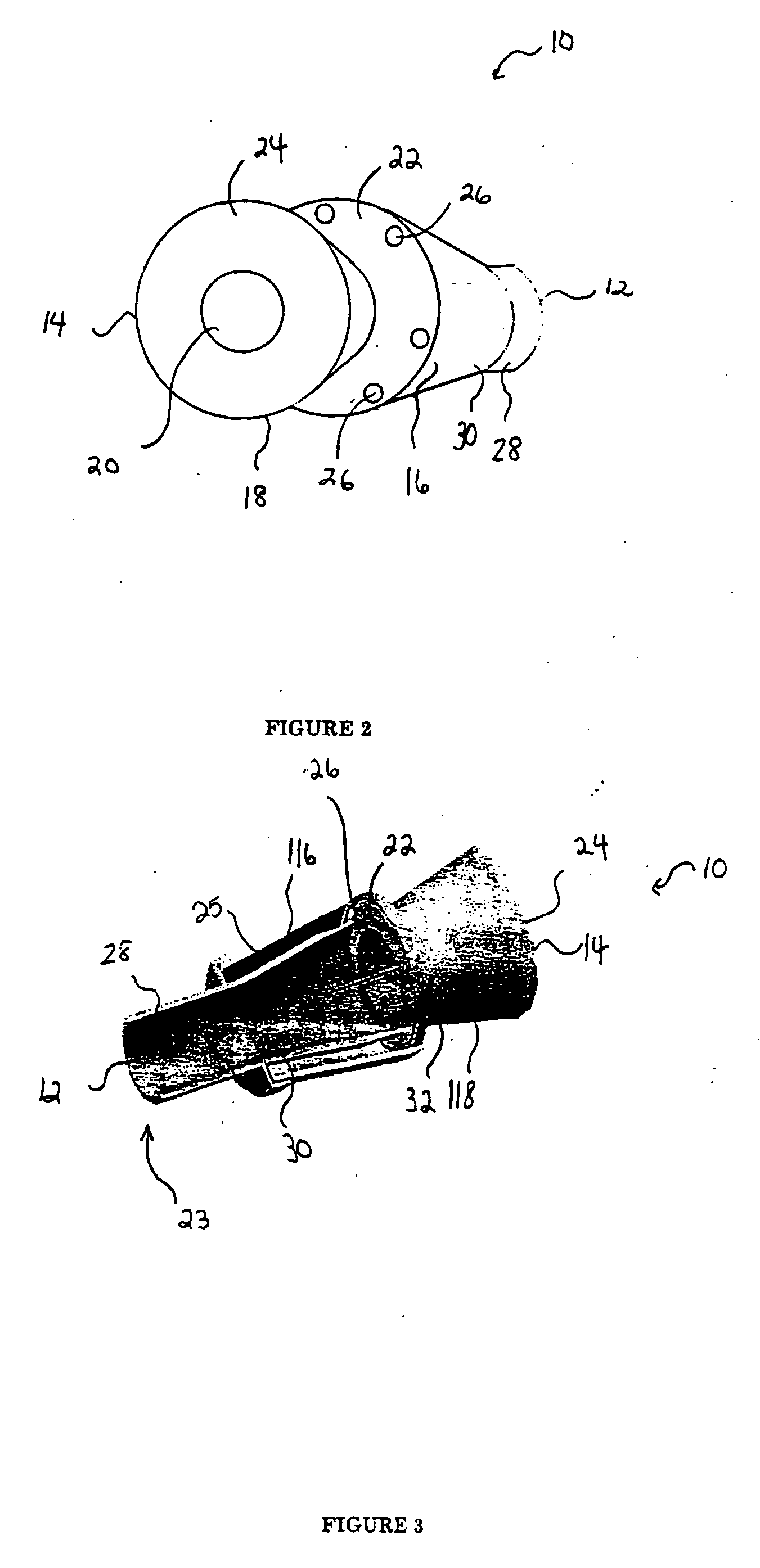
[0034] Referring to FIGS. 1 and 2, the spacer of the present invention 10 includes spacer walls defining a first conical body 16 having a small diameter proximal end 30, a large diameter distal end 34, and a distal end surface 22. The central portion of the distal end surface 22 of the first conical body is joined to, and in fluid communication with, a small diameter proximal end 32 of a second conical body 18. The first and second conical bodies 16, 18 have respective first and second internal chambers 116, 118 that generally define a continuous spray conduit 11 through the spacer 10 from the distal end 14 of the second conical body 18 to the proximal end 30 of the first conical body 16. Preferably, a mouthpiece 28 will be formed in (or attached to) the proximal end 30 of the first conical body 16 such that the spray conduit 11 extends to the proximal end 12 of the spacer 10. A spray inlet 20 (FIG. 2) for attachment of an MDI or other medication dispensing inhaler is centrally prov...


PUM


Abstract

A spacer for delivering a medication spray from a metered dose inhaler includes a first conical body joined to a second conical body, forming a continuous spray conduit through first and second internal chambers of the respective first and second conical bodies. A mouthpiece is formed in the small diameter (proximal) end of the first conical body. A spray inlet for attachment to an MDI or similar device is formed at the large diameter (distal) end of the second conical body. A plurality of air inlets are placed downstream of the medication inlet proximate to, or in, the large diameter distal end surface of the first conical body. During use, high-pressure recirculation zones are created in the first and second chambers, near the spray inlet and the air inlets, and an air jacket is created along the inner surface of the wall of the first conical body. This forces the medication spray through the spacer into a defined, central airflow path through the spray conduit, minimizing particle deposition by contact with the walls of the spacer.

Description

STATEMENT REGARDING FEDERALLY SPONSORED RESEARCH OR DEVELOPMENT [0001] Work on this invention was performed under NIH Grant R44HL64500-03 titled “Development of an Improved Pediatric Spacer for Inhalers” during the period May 2000 through November 2000 and from October 2002 through the date of filing. Accordingly, the U.S. Government may have rights in the invention.[0002] A portion of the disclosure of this patent document contains material that is subject to copyright protection. The copyright owner has no objection to the facsimile reproduction by anyone of the patent document or the patent disclosure, as it appears in the U.S. Patent and Trademark Office patent file or records, but otherwise reserves all copyright rights whatsoever. CROSS-REFERENCES TO RELATED APPLICATIONS [0003] Not Applicable REFERENCE TO SEQUENCE LISTING OR COMPUTER PROGRAM LISTING APPENDIX [0004] Not Applicable BACKGROUND OF THE INVENTION [0005] The present invention relates generally to devices for use in o...

Claims


Application Information

Patent Timeline
Patent Type & Authority Applications(United States)
IPC IPC(8): A61M11/00A61M15/00
CPCA61M15/0016A61M15/0086
Inventor SUNDARAM, SHIVSHANKARPRABHAKARPANDIAN, BALABHASKARMAKHIJANI, VINODPRZEKWAS, ANDRZEJ
Owner CFD RES CORP
Why Eureka
Try Eureka