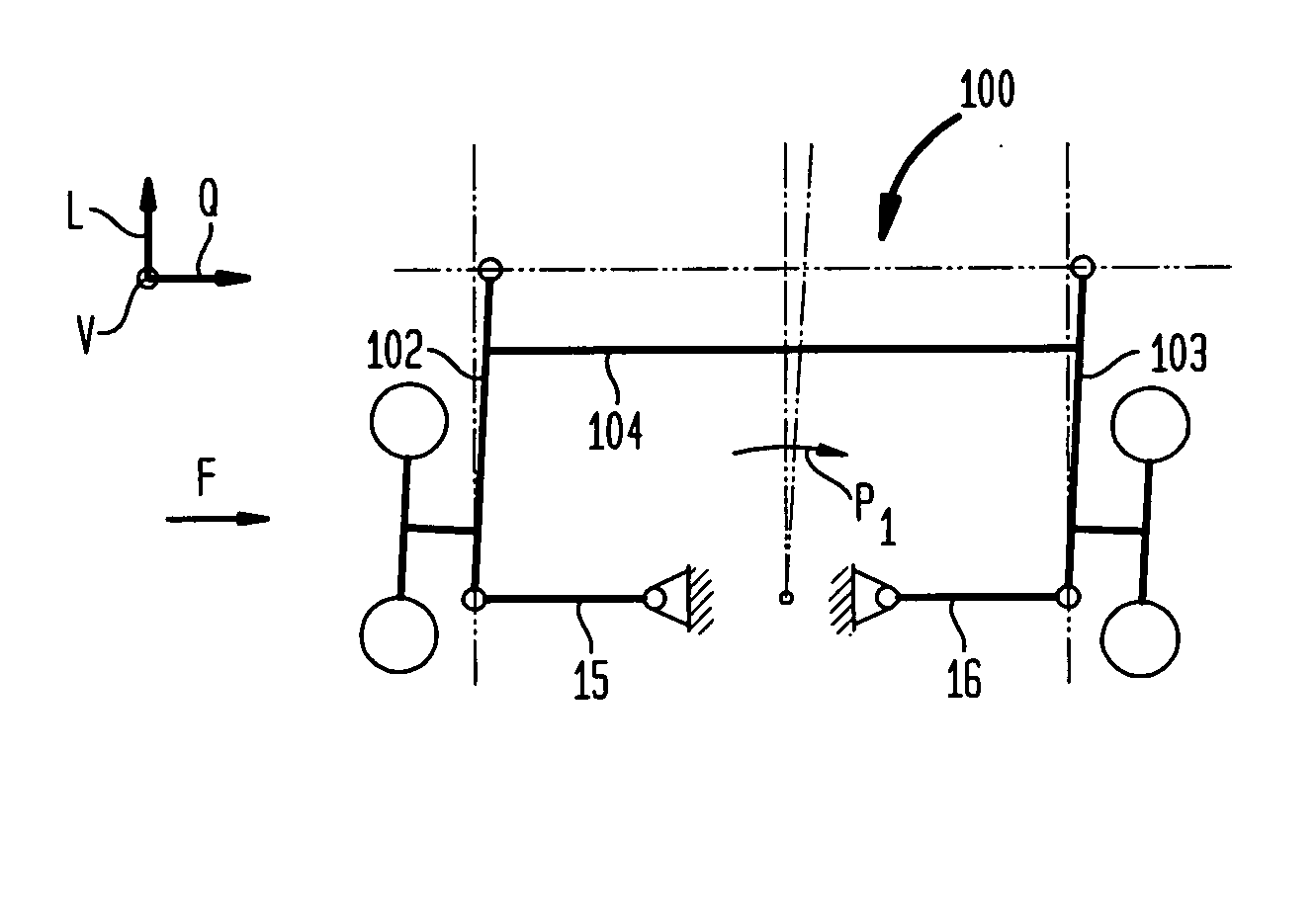
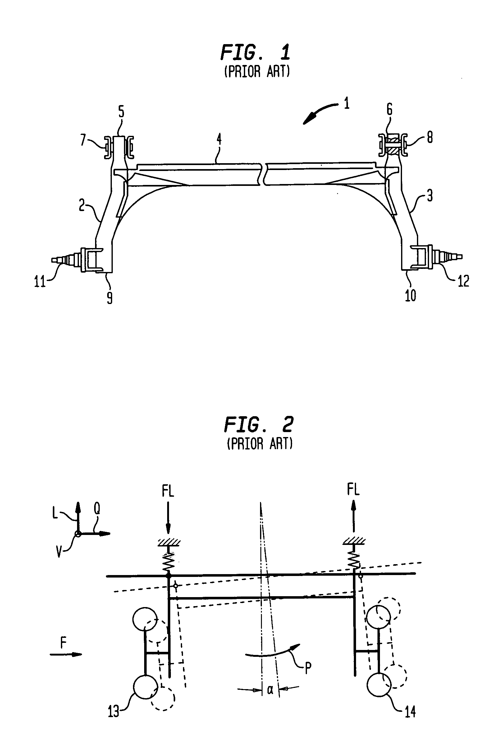
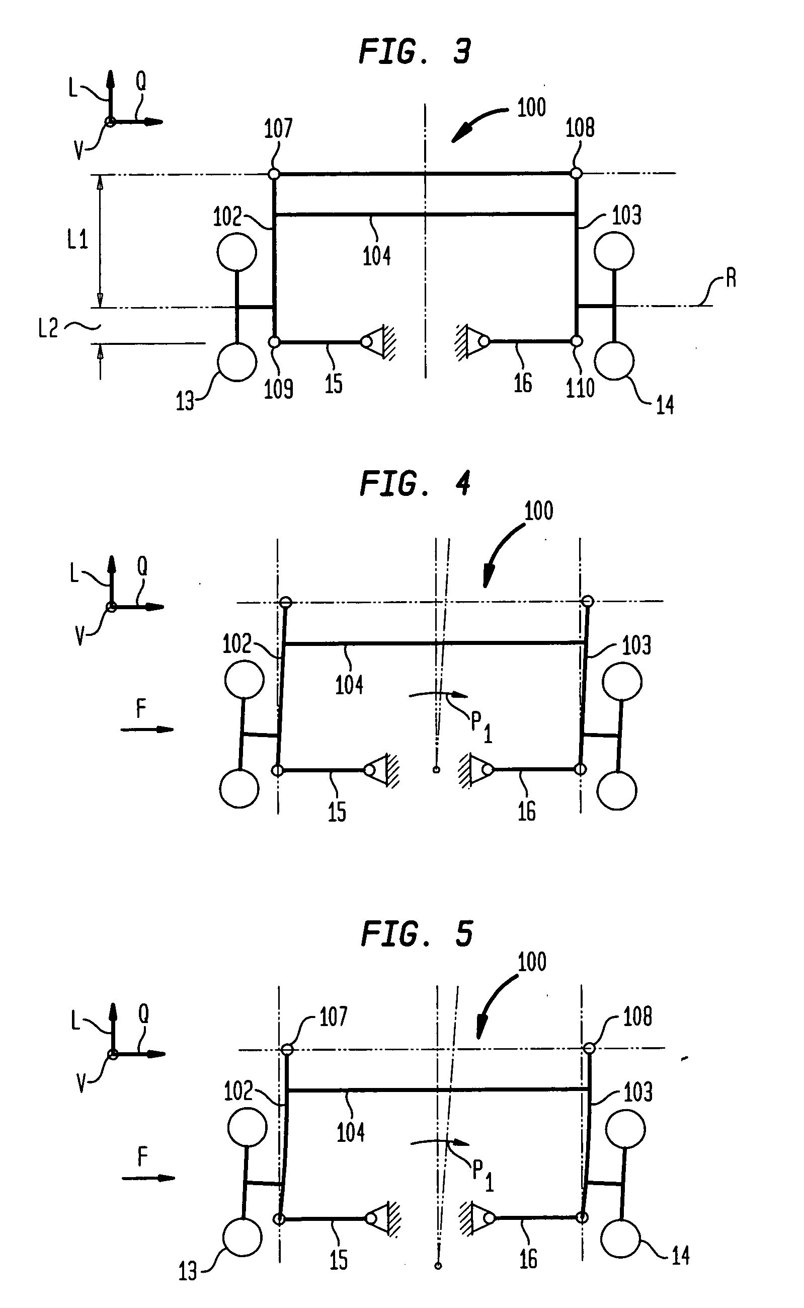
[0012] Transverse control arms absorb a majority of introduced lateral forces during cornering to thereby provide a
toe correcting function to adjust
toe at least of the outer wheel in the curve so as to counteract oversteer of the motor vehicle. The additional transverse control arms transmit little lateral forces onto the primary bearings. As a consequence, the primary bearings can be constructed with little transversal rigidity, without adversely affecting the driving behavior. Little transversal rigidity may even be desired in accordance with the present invention in order to allow a shift of the front ends of the longitudinal control arms transversely to the travel direction so that this toe correcting function is able to realize an additional toe adjustment that acts against oversteer. It is hereby suitable to construct the transverse control arms relatively hard, i.e. transversely rigid, in order to realize the desired toe correction by transverse shift in the primary bearings, and to prevent the entire torsion suspension from shifting in parallel relationship to the initial disposition. Rather, a kinematic
system is desired in which a
parallelogram shiftable in the area of the primary bearing is displaced with a fix point in midsection between the transverse control arms.
[0014] According to another feature of the present invention, the longitudinal control arms are defined by a longitudinal axis extending in a longitudinal direction, a
transverse axis extending transversely to the travel direction, and a
vertical axis extending upwards in perpendicular relationship to the longitudinal axis and in perpendicular relationship to the
transverse axis, wherein the longitudinal control arms may have at least one length section which extends between a connection area of the torsion axle and the transverse control arms and has a bending resistance which is smaller with respect to bending stress about the
vertical axis than with respect to bending stress about the
transverse axis. Compared to conventional twist beam suspensions without additional transverse
control arm, a torsion suspension according to the invention encounters significantly smaller bending moments about the
vertical axis of the longitudinal control arms when exposed to lateral forces. As a result, the longitudinal control arms can be constructed more flexible in relation to their vertical axis than in conventional twist beam suspensions. Of course, the longitudinal control arms should be constructed rigid enough in relation to flexure about the transverse axis in order to allow introduction of moments into the torsion suspension and via the torsion suspension into the second longitudinal
control arm for realizing the desired compression characteristic. The longitudinal control arms can thus be configured to have a greater resistance to flexure about their transverse axis than to flexure about their vertical axis. As a consequence of the force conditions acting in the longitudinal control arms, it is possible to save significant material in the area of the longitudinal control arms.
[0015] In general, it is also possible to adjust the resistance against flexure in longitudinal control arms of
metal through targeted local heat treatment, without requiring significant geometric modification of known constructions. For weight-saving reasons, it is, however, currently preferred to use longitudinal control arms which, when undergoing flexure, have a
section modulus which is smaller in relation to the vertical axis than a
section modulus of the transverse control arms undergoing flexure. The
section modulus depends substantially on a cross sectional construction of the longitudinal control arms. As a result of the desired section moduli, a torsion suspension according to the present invention can be configured such as to extend in cross section spatially less in direction of its transverse axis than in direction of its vertical axis. The longitudinal
control arm may, for example, be implemented by a relatively high rectangular profile with slight width, with the section moduli of the longitudinal control arm undergoing flexure being dimensioned in such a manner that the longitudinal control arm is targeted to undergo flexure about its vertical axis on turns. Thus, the toe of the rear wheel changes not only as a result of lateral shift of the primary bearings but also as a result of flexure of the longitudinal control arms about their respective vertical axis. Although any weight saving in the area of the longitudinal control arms is compensated in part by the provision of additional transverse control arms, a lower weight is overall realized while significantly improving toe guidance and spring characteristic of the torsion suspension.
[0016] The transverse control arms may extend at any angle deviating from 90° in relation to the longitudinal control arms. Currently preferred is however an arrangement of the transverse control arms transversely to the travel direction. In this way, the fraction of normal forces is the greatest in the bearing areas of the transverse control arms upon the vehicle body and the longitudinal control arms, and there is no need to absorb any additional shearing forces which can be absorbed, as usual, by the primary bearings.
[0017] According to another feature of the present invention, the transverse control arms may have each at least two struts, with each strut hinged to the vehicle body, on one hand, and hinged to a corresponding one of the longitudinal control arms, on the other hand. Suitably, the section modulus in relation to torsion may also be reduced, when the section modulus is reduced in relation to flexure so that the wheel camber changes as a result of torsion of the longitudinal control arms during compression. The two link struts may be articulated to the longitudinal control arms at different levels, thereby defining upper and lower struts, so as to compensate for undesired changes in camber. Suitably, the upper and lower struts may have different lengths in order to influence the compression behavior in a desired manner. In other words, the upper strut may be shorter than the lower strut, or vice versa. Depending on the encountered lateral force and depending on the degree of compression, the wheel may undergo a forced toe adjustment and change in camber. An essential
advantage of this configuration of a torsion suspension according to the invention resides in the fact that toe adjustment or change in camber can be used as toe correcting function or camber correction function in a desired manner and independently from one another in a very cost-efficient manner.
[0022] A torsion suspension as a type of an expanded twist beam suspension combines advantageous driving dynamics of a multilink wheel suspension with the advantages in cost, packaging and weight of twist beam suspension.


