
Method and/or apparatus for high speed visualization of depth image-based 3D graphic data

Inactive Publication Date: 2005-08-11
SAMSUNG ELECTRONICS CO LTD
View PDF12 Cites 38 Cited by
  • Summary
  • Abstract
  • Description
  • Claims
  • Application Information

AI Technical Summary

Benefits of technology

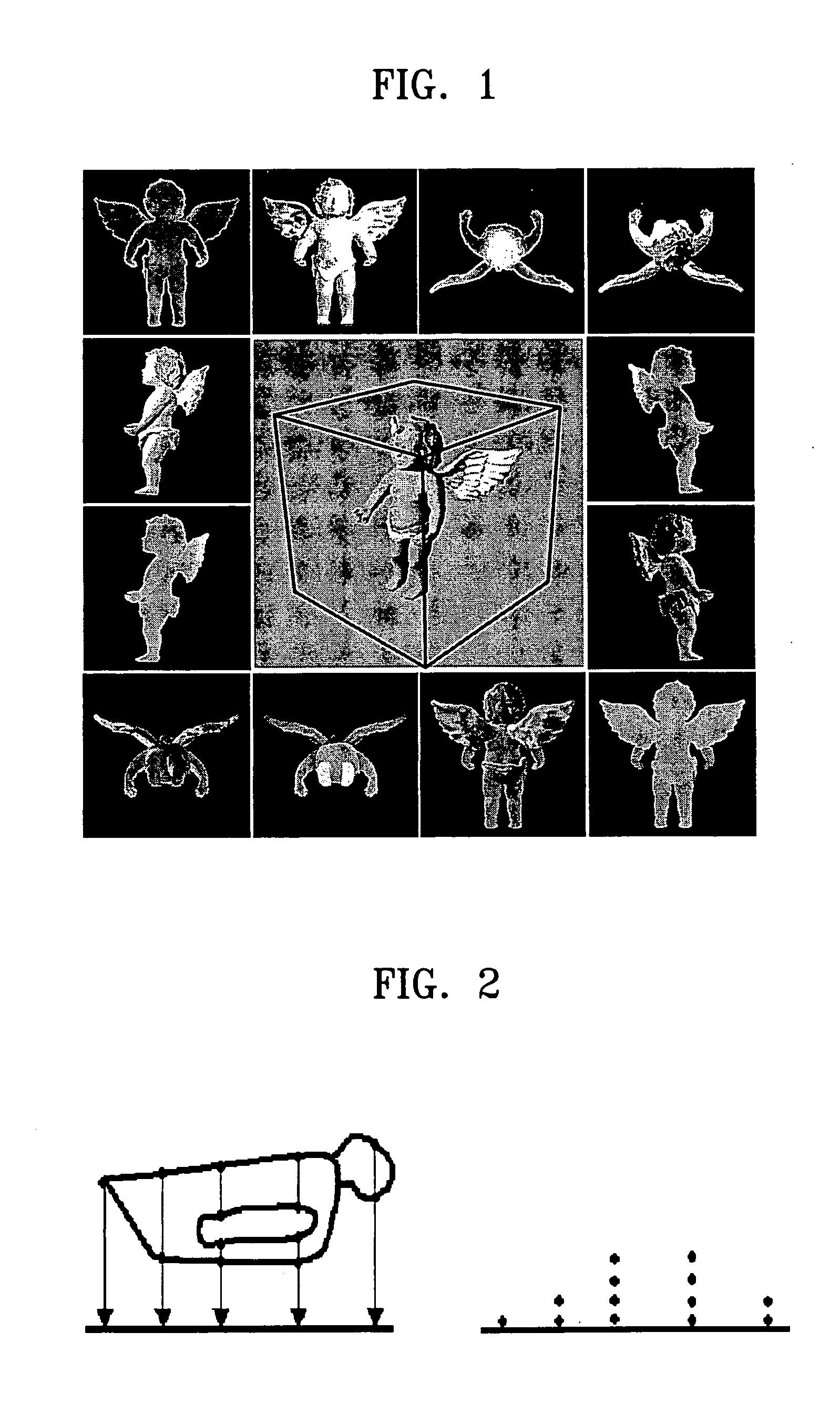
[0014] Embodiments of the present invention provide a method and an apparatus for high speed visualization of depth image-based three-dimensional (3D) graphic data represented by one of a simple texture, a point texture, and an octree image to reduce memory usage and increase a visualization speed.
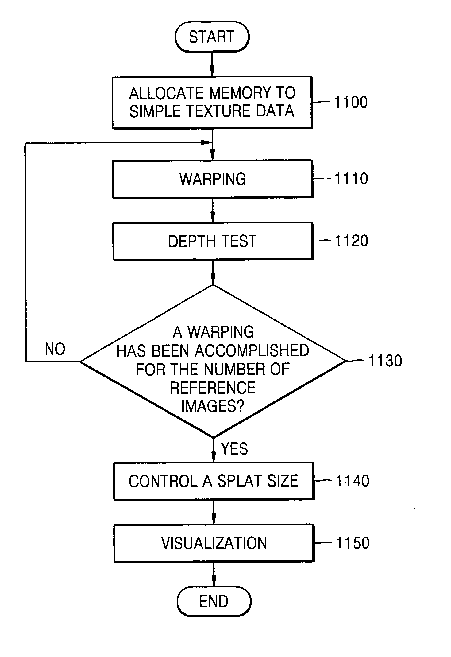
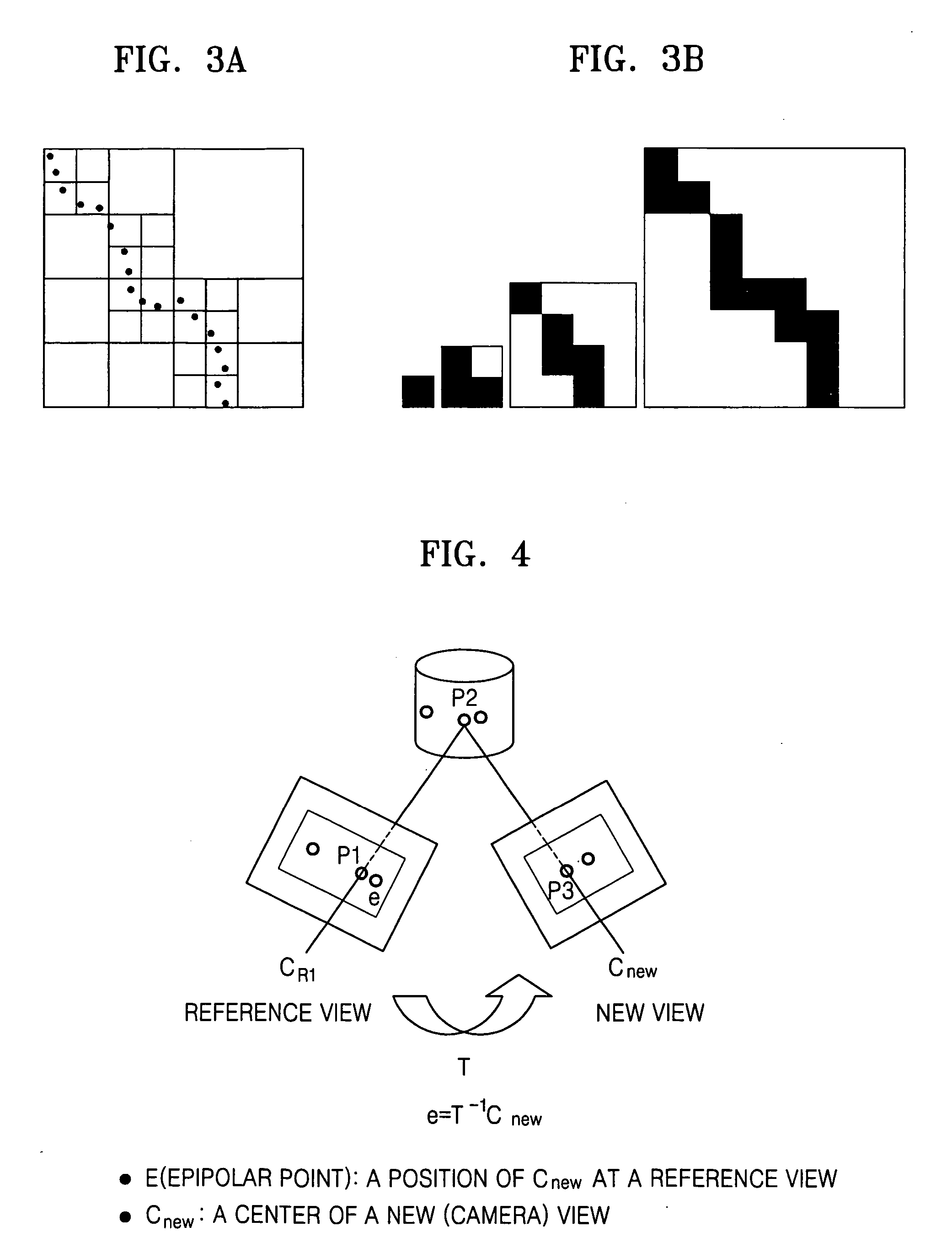
[0019] The coordinate transformation may be accomplished by fixed-point arithmetic operation of a floating-point arithmetic operation. The fixed-point arithmetic operation may include: converting the floating-point number to the corresponding fixed-point number; performing a coordinate transformation using the converted fixed-point number; and converting the result of the coordinate transformation to a floating-point representation. The performing a depth test may include: storing depth and color values, obtained by the warping operation for the first reference image, in a front depth buffer and a front color buffer, respectively; storing depth and color values, obtained by the warping operation for the second reference image, in a back depth buffer and a back color buffer, respectively; comparing the depth value stored in the front depth buffer with the depth value stored in the back depth buffer; substituting the depth value stored in the front depth buffer and the color value stored in the front color buffer with the depth value stored in the back depth buffer and the color value stored in the back color buffer, respectively, if the depth value stored in the front depth buffer is larger than the depth value stored in the back depth buffer as a result of the comparison; and iterating from the storing the depth and color values through the substituting the depth and color values with respect to all warping images. The operation of performing the depth test may further include adaptively controlling a splat size depending on a distance from a predetermined view point to a 3D object and the operation of visualizing the object is accomplished by using the depth data, the color data, and the appropriately sized splat. The operation of adaptively controlling the splat size includes: determining an initial splat size by comparing a resolution of the reference image with a resolution of a destination image; and adjusting the initial splat size according to an enlargement / reduction ratio of a zoom-in / zoom-out operation to create the destination image. In the operation of determining the initial splat size, the splat size may be set to 1 if the resolution of the destination image is smaller than or equal to the resolution of the reference image, and the splat size may be set to an average enlargement aspect ratio if the resolution of the destination image is larger than the resolution of the reference image. In the operation of adjusting the initial splat size, the splat size may be enlarged by a zoom ratio so as to prevent a “hole” phenomenon during the zoom-in, and reduced by the zoom ratio so as to retain visualization quality of a predetermined level during the zoom-out.

Problems solved by technology

However, unlike typical personal computers, there have been severe problems in attempting to apply 3D graphics to a mobile device.
First, the CPUs usually don't have enough processing power.
Second, the mobile CPUs do not support floating-point arithmetic operations.
Third, the mobile CPUs also don't have hardware 3D graphics accelerators either.
For these reasons, it is very difficult to render 3D object at an interactive frame rate on mobile devices.
Furthermore, the rendering complexity for synthesizing a new scene is proportional to the number of pixels, not to the complexity of the scene.
On the other hand, in the fields of portable apparatuses, there has not been sufficient research in such high-speed visualization of a 3D graphic object by using the image-based representation.

Method used


Image

  • Method and/or apparatus for high speed visualization of depth image-based 3D graphic data
  • Method and/or apparatus for high speed visualization of depth image-based 3D graphic data
  • Method and/or apparatus for high speed visualization of depth image-based 3D graphic data

Examples


Embodiment Construction

[0051] Reference will now be made in detail to the embodiments of the present invention, examples of which are illustrated in the accompanying drawings, wherein like reference numerals refer to the like elements throughout. The embodiments are described below to explain the present invention by referring to the figures.

[0052] Embodiments of the present invention may, however, also be embodied in many different forms and should not be construed as being limited to the embodiments set forth herein; rather, these embodiments are provided so that this disclosure will be thorough and complete, and will fully convey the concept of the invention to those skilled in the art. Like reference numerals in the drawings denote like elements, and thus their description will not be repeated.

[0053] Now, a method and / or an apparatus for high speed visualization of a depth image-based 3D graphic data, according to embodiments of the present invention, will be described with reference to the attached...


PUM

PropertyMeasurementUnit
Sizeaaaaaaaaaa
Areaaaaaaaaaaa
Depthaaaaaaaaaa

Abstract

A method and / or apparatus for high speed visualization of depth image-based 3D graphic data. The method includes: reading point texture data of a 3D object; performing a 3D warping for each of the reference images of the simple texture data at a predetermined view point to obtain warped images; performing a depth test and a splatting for each pixel of the plurality of warped images to obtain final color data; and visualizing an object by using the final color data. Accordingly, it is possible to reduce memory usage and increase the number of visualization per a second and to effectively implement visualization of 3D graphic object in, particularly, a mobile terminal.

Description

CROSS-REFERENCE TO RELATED APPLICATION [0001] This application claims the benefit of Korean Patent Application No. 10-2004-0008741, filed on Feb. 10, 2004, in the Korean Intellectual Property Office, the disclosure of which is incorporated herein in its entirety by reference. BACKGROUND OF THE INVENTION [0002] 1. Field of the Invention [0003] The present invention relates to a three-dimensional (3D) graphics, and more particularly, to a method for and / or an apparatus for high-speed visualization of a depth image-based 3D graphic data. [0004] 2. Description of the Related Art [0005] Initially, the ultimate goal of 3D graphics is to synthesize realistic graphic images with equal realism compared with the real world. Conventionally, a polygonal mesh is widely used in 3D computer graphics to represent a 3D object, with which any arbitrary shape of object can be modeled properly. Due to the advances in a graphics algorithm and a graphics processing unit (GPU), even very complex objects o...

Claims


Application Information

Patent Timeline
IPC IPC(8): G06T13/40G06T17/00
CPCG06T15/04G06T15/205G06T15/10D04D9/06D06Q1/10
Inventor PARK, INKYUJANG, GYEONGIAHAN, JOOYEONJUNG, SEOKYOONKIM, KEUNHO
Owner SAMSUNG ELECTRONICS CO LTD
Features
  • Generate Ideas
  • Intellectual Property
  • Life Sciences
  • Materials
  • Tech Scout
  • Unparalleled Data Quality
  • Higher Quality Content
  • 60% Fewer Hallucinations
Learn More