Disposable flashlight

Inactive Publication Date: 2005-08-11
GOSWAMI VINOD KUMAR +1
View PDF12 Cites 1 Cited by
  • Summary
  • Abstract
  • Description
  • Claims
  • Application Information

AI Technical Summary

Benefits of technology

[0010] Another object of the present invention is to provide a disposable water-activated flashlight that is cost effective to manufacture.
[0011] Yet another object of the present invention is to provide a disposable water-activated flashlight

Problems solved by technology

A significant problem with the conventional flashlights is their unreliability in moisture and wet conditions.
The circuit may be shorted and the flashlight rendered inoperable.
During storage, the batteries may be weakened due to current leakage, and the switch mechanisms corroded.
Such batterie

Method used


Image

  • Disposable flashlight
  • Disposable flashlight
  • Disposable flashlight

Examples


Example

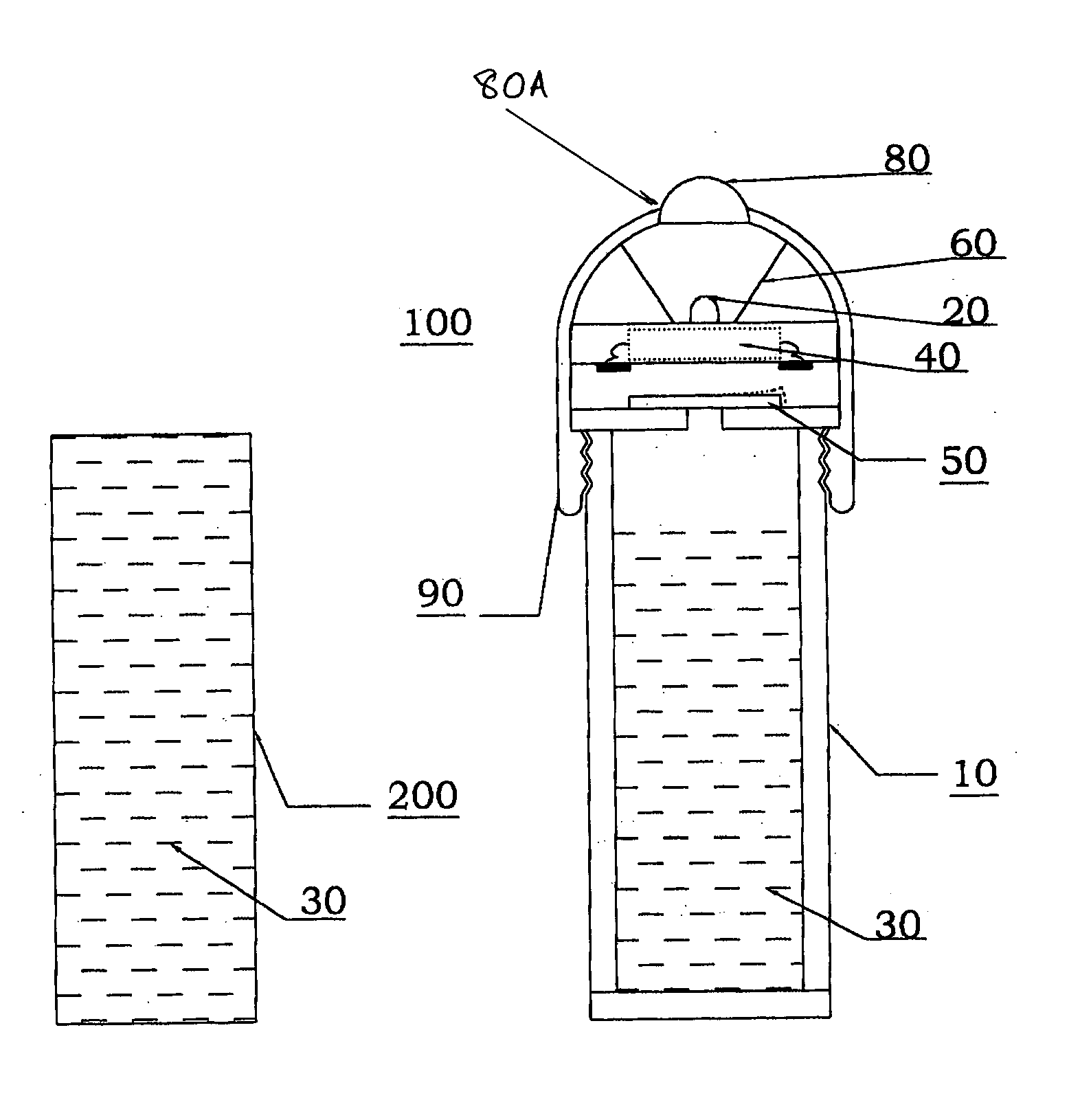
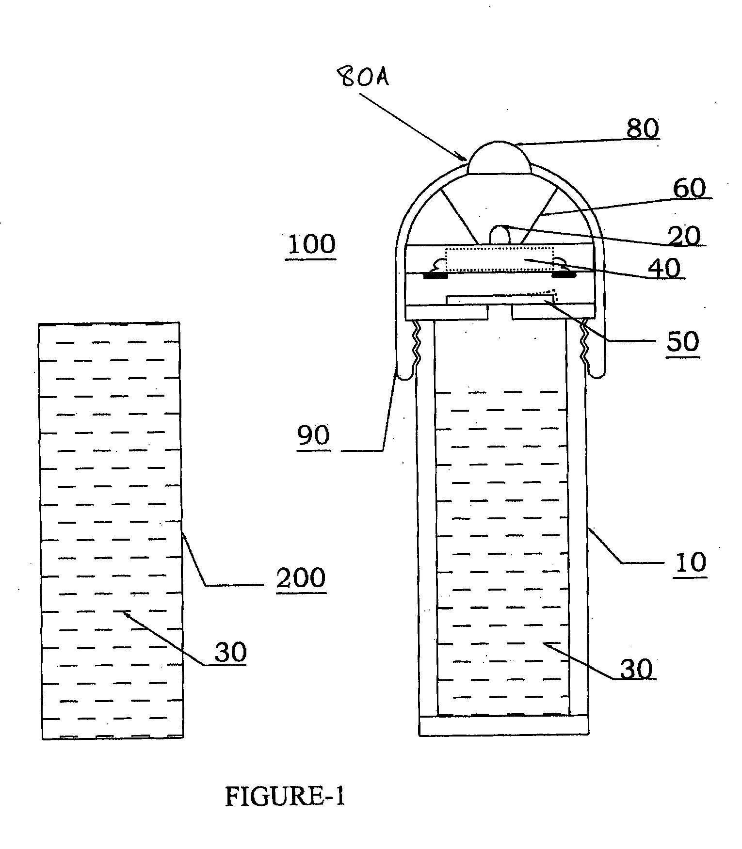
[0023]FIG. 1 presents a schematic view of the disposable flashlight comprising the present invention: a housing 10, a light bulb 20, a water- or other electrically conducting fluid medium 30, a battery 40 for energizing the bulb 20, a switch 50 that allows the battery 40 to power the light bulb 20 using said water or other fluid 30, and means 90 for capturing the light bulb 20, fluid 30, and battery 40. A reflector 60 and lens 80 are optionally provided to help direct the light from the light bulb 20 and are within the scope of the present invention. A container 200 made from a low rupture strength material, such as a thin plastic membrane, within which the conducting fluid 30 may be packaged and sealed, is optionally provided for assembly into said housing 10.

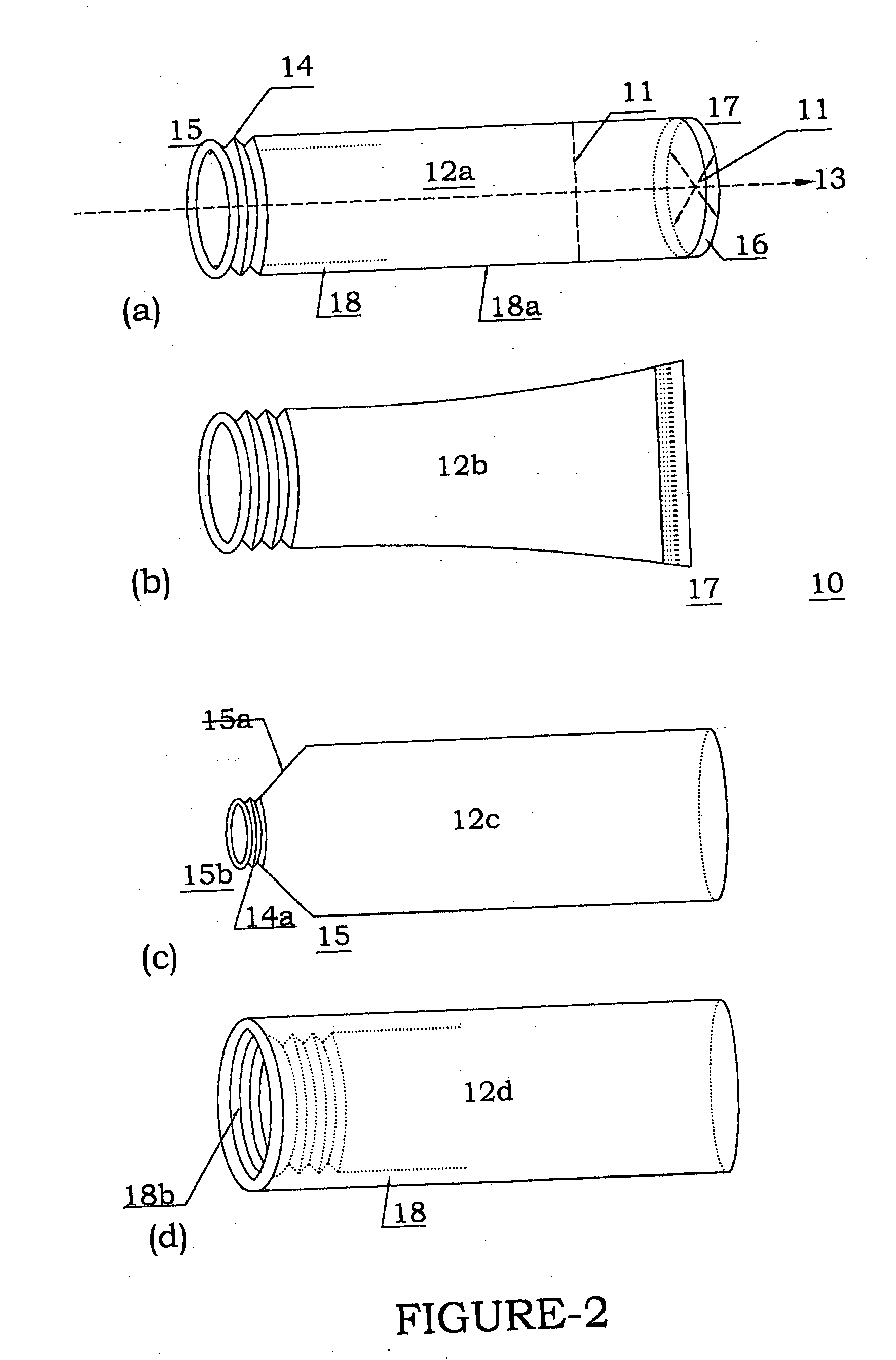
[0024] The housing 10 may be of single piece construction, but is preferably provided in two parts, a first housing 10 and a second housing 110. (FIGS. 2 and 4). Although the first and second housing parts 10 and 110 may be c...


PUM


Abstract

A disposable flashlight uniquely suited to operation in high humidity and water exposure conditions, such as those encountered in search and rescue missions at sea. The bulb, which is preferably a high intensity super-bright light emitting diode, is energized to produce light using a battery connected to it via a switch and an electrical circuit. The switch completes the electrical circuit via an electrically conducting fluid, allowing the electrical current to flow from the battery and the bulb to illuminate.

Description

[0001] This application claims the benefit of U.S. Provisional Application No. 60 / 543,149 filed on Feb. 10, 2004.BACKGROUND OF THE INVENTION [0002] The present invention relates generally to a disposable flashlight and more specifically to a disposable fluid-activated flashlight suited to normal usage as well as emergency situations. [0003] Disposable flashlights have been in use for years. Examples of such devices are described in U.S. Pat. Nos. 3,796,869, 4,122,510, 4,429,352 and 4,939,626. Typically, the flashlight has a housing, battery, bulb, and switch. The bulb is lit via the switch, located on the housing of the flashlight, which completes the electrical circuit and allows the current from the battery to energize and illuminate the bulb. [0004] A significant problem with the conventional flashlights is their unreliability in moisture and wet conditions. The circuit may be shorted and the flashlight rendered inoperable. During storage, the batteries may be weakened due to cur...

Claims


Application Information

Patent Timeline
IPC IPC(8): F21L4/02F21S4/00F21V23/04
CPCF21L4/027F21Y2101/02F21V23/0414F21Y2115/10
Inventor GOSWAMI, VINOD KUMARGOSWAMI, VINITA
Owner GOSWAMI VINOD KUMAR
Why Eureka
Try Eureka