
System and method for measuring the linear and rotational acceleration of a body part

Inactive Publication Date: 2005-08-11
RIDDELL
View PDF63 Cites 81 Cited by
  • Summary
  • Abstract
  • Description
  • Claims
  • Application Information

AI Technical Summary

Benefits of technology

[0023] The system and method of the present invention offers the opportunity to study head acceleration, human tolerance limits, the range and direction of accelerations in humans in relation to morphological features (e.g., neck circumference, head volume, neck length), and the relationship between precise measures of head acceleration in linear and rotational directions and acute consequence to brain physiology and function. Moreover, it provides the ability to measure an individual's cumulative exposure to linear and rotational accelerations while allowing unaffected performance of everyday sports and activities.
[0028] Because of its portability, small size, and convenient light weight, the system and associated method of the present invention can also be used to study the acceleration of the body parts of live animals. For example, the acceleration and deceleration of birds in flight could be studied with a modified version of the present invention.
[0030] It is a further object of the invention to provide an inexpensive system that can still achieve results which are within the acceptable range of error for the given scientific question, study or hypothesis.
[0031] Another object of the present invention is to provide a system and method of calculating and estimating the linear and rotational acceleration that is easy to install and is comfortable for the individual to wear without affecting their game play either in a helmet or head band environment.
[0032] It is yet another object of the present invention to provide a system and method of measuring and calculating the linear and rotational acceleration that can be installed commercially at low cost. Other features and advantages of the invention will be apparent from the following specification taken in conjunction with the following drawings.

Problems solved by technology

During such physical activity, the head or other body part of the individual, is often subjected to direct contact to the head which results in impact to the skull and brain of the individual as well as movement of the head or body part itself.
The conventional application of known forces and / or measurement of forces applied to animals, cadavers, crash dummies, and human volunteers limit our knowledge of a relationship between forces applied to a living human head and resultant severe and catastrophic brain injury.
These prior studies have limited value as they typically relate to research in the automobile safety area.
MTBI is a major source of lost player time.
Concussions, particularly when repeated multiple times, significantly threaten the long-term health of the athlete.
The National Center for Injury Prevention and Control considers sports-related traumatic brain injury (mild and severe) an important public health problem because of the high incidence of these injuries, the relative youth of those being injured with possible long term disability, and the danger of cumulative effects from repeat incidences.
Athletes who suffer head impacts during a practice or game situation often find it difficult to assess the severity of the blow.
Subsequent impacts following an initial concussion (MTBI) may be 4-6 times more likely to result in a second, often more severe, brain injury.
Yet there are no objective biomechanical measures directly related to the impact used for diagnostic purposes.
Brain injury following impact occurs at the tissue and cellular level, and is both complex and not fully understood.
Head acceleration induces strain patterns in brain tissue, which may cause injury.
There is significant controversy regarding what biomechanical information is required to predict the likelihood and severity of MTBI.
Direct measurement of brain dynamics during impact is extremely difficult in humans.
There is a critical lack of information about what motions and impact forces lead to MTBI in sports.
A limitation of the prior art involves practical application and widespread use of measurement technologies that are size and cost effective for individuals and teams.
Tri-axial accelerometer systems require that the accelerometers be orthogonal to each other Also, such tri-axial accelerometer systems have been extremely expensive making it cost prohibitive for widespread commercial installation on an entire team.
It is impractical, from a size, cost and complexity standpoint, for commercial application of such arrays in helmet or head mounted systems.
Obviously, accelerometer arrays for measuring linear and rotational accelerations cannot be readily mounted inside the human head, as is done with instrumented test dummy heads.
Other sensing technologies, such as gyroscopes, magnetohydrodynamic angular rate sensors and GPS sensors, do not currently fulfill the practical and technical specifications for a commercially available system.
Also, the use of multi-axis accelerometer systems placed in a mouthguard are impractical because wires need to run from the helmet or backpack into the user's mouth from the power source and to a telemetry unit, which might present a hazard to the players and limited compliance among them.

Method used


Image

  • System and method for measuring the linear and rotational acceleration of a body part
  • System and method for measuring the linear and rotational acceleration of a body part
  • System and method for measuring the linear and rotational acceleration of a body part

Examples


Embodiment Construction

[0043] While this invention is susceptible of embodiments in many different forms, there is shown in the drawings and will herein be described in detail preferred embodiments of the invention with the understanding that the present disclosure is to be considered as an exemplification of the principles of the invention and is not intended to limit the broad aspect of the invention to the embodiments illustrated.

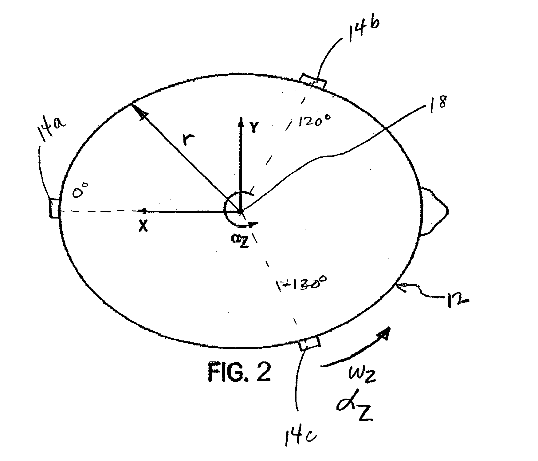
[0044] The present invention provides a system and method for measuring, i.e. estimating, the linear and rotational acceleration of a body part. For ease of illustration, the body part will be described below as a human head. Unlike the prior art, the present invention uses single axis accelerometers orthogonal to the surface of the body part and not necessarily orthogonal to each other to enable the estimation of both the linear acceleration and rotational acceleration of the body part.

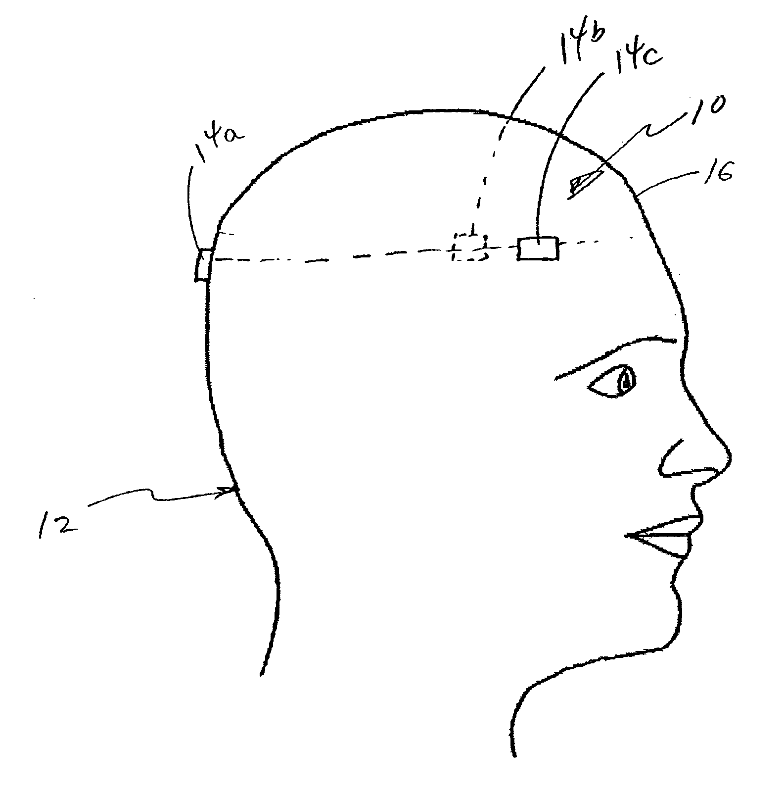
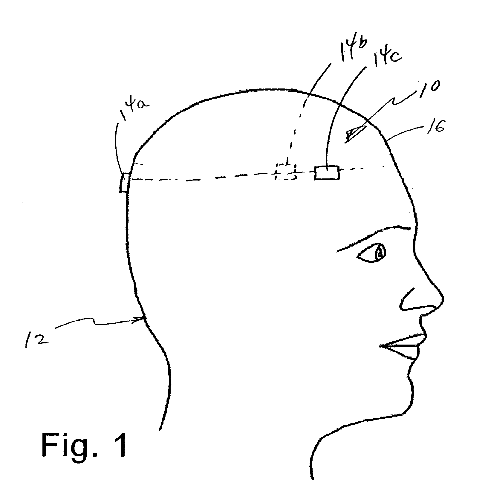
[0045] Referring first to FIG. 1, a side view of an installed system 10 of the preferred ...


PUM


Abstract

A system and method for determining the magnitude of linear and rotational acceleration of and direction of impact to a body part, such as a head includes positioning a number of single-axis accelerometers proximate to the outer surface of the body part. A number of accelerometers are oriented to sense respective linear acceleration orthogonal to the outer surface of the body part. The acceleration data sensed is collected and recorded. A hit profile function is determined from the configuration of the body part and the positioning of the plurality of accelerometers thereabout. A number of potential hit results are generated from the hit profile function and then compared to the acceleration data sensed by the accelerometers. One of the potential hit results is best fit matched to the acceleration data to determine a best fit hit result, which yields the magnitude of linear acceleration to and direction of an impact to the body part. The rotational acceleration of the body part can also be estimated from the magnitude of linear acceleration of and direction of the impact to the body part.

Description

CROSS-REFERENCE TO RELATED APPLICATIONS [0001] This application is a Continuation of co-pending application Ser. No. 09 / 974,566, filed Oct. 10, 2001, which claims the benefit of the Provisional Application No. 60 / 239,379, filed Oct. 11, 2000.FEDERALLY SPONSORED RESEARCH OR DEVELOPMENT [0002] The invention described herein was made in the course of work under grant number 1R43HD4074301 from the National Institutes of Health. The U.S. Government may retain certain rights in this invention.BACKGROUND OF THE INVENTION [0003] The present invention relates to recording of the magnitude and direction of impact to and the linear and rotational acceleration of a body part, such as a human head, of person engaged in physical activity, such as during the play of a sport. [0004] More particularly, it relates to a helmet based system which is typically worn while playing a sport such as football or hockey, and to the method of recording and storing data relating to the linear and rotational acce...

Claims


Application Information

Patent Timeline
IPC IPC(8): A61B5/11A63B71/06A63B71/10
CPCA42B3/046A61B5/11A61B5/6814A63B71/06A63B71/10A63B2208/12A61B5/7475A63B2243/007A61B5/6803A61B5/0004A61B5/7246A61B5/742A63B2230/60A61B5/4076A42B3/125A61B5/1121A63B2220/40
Inventor CRISCO, JOSEPH J. IIIGREENWALD, RICHARD M.
Owner RIDDELL
Learn More