Arbitration system having a packet memory and method for memory responses in a hub-based memory system

a hub-based memory and packet memory technology, applied in computing, instruments, electric digital data processing, etc., can solve the problems of slow memory controller limiting the data bandwidth between processors and memory devices, and increasing operating speed that has not kept pace with processor increases

Active Publication Date: 2005-08-11
MICRON TECH INC
View PDF99 Cites 71 Cited by
  • Summary
  • Abstract
  • Description
  • Claims
  • Application Information

AI Technical Summary

Problems solved by technology

Although the operating speed of memory devices has continuously increased, this increase in operating speed has not kept pace with increases in the operating speed of processors.
The relatively slow speed of memory controllers and memory devices limits the data bandwidth between the processor and the memory devices.
In addition to the limited bandwidth between processors and memory devices, the performance of computer systems is also limited by latency problems that increase the time required to read data from system memory devices.
Therefore, although SDRAM devices can synchronously output burst data at a high data rate; the delay in initially providing the data can significantly slow the operating speed of a computer system using such SDRAM devices.
Although computer systems using memory hubs may provide superior performance, they nevertheless may often fail to operate at optimum speeds for a variety of reasons.
For example, even though memory hubs can provide computer systems with a greater memory bandwidth, they still suffer from latency problems of the type described above.
More specifically, although the processor may communicate with one memory device while another memory device is preparing to transfer data, it is sometimes necessary to receive data from one memory device before the data from another memory device can be used.
In the event data must be received from one memory device before data received from another memory device can be used, the latency problem continues to slow the operating speed of such computer systems.

Method used


Image

  • Arbitration system having a packet memory and method for memory responses in a hub-based memory system
  • Arbitration system having a packet memory and method for memory responses in a hub-based memory system
  • Arbitration system having a packet memory and method for memory responses in a hub-based memory system

Examples


Embodiment Construction

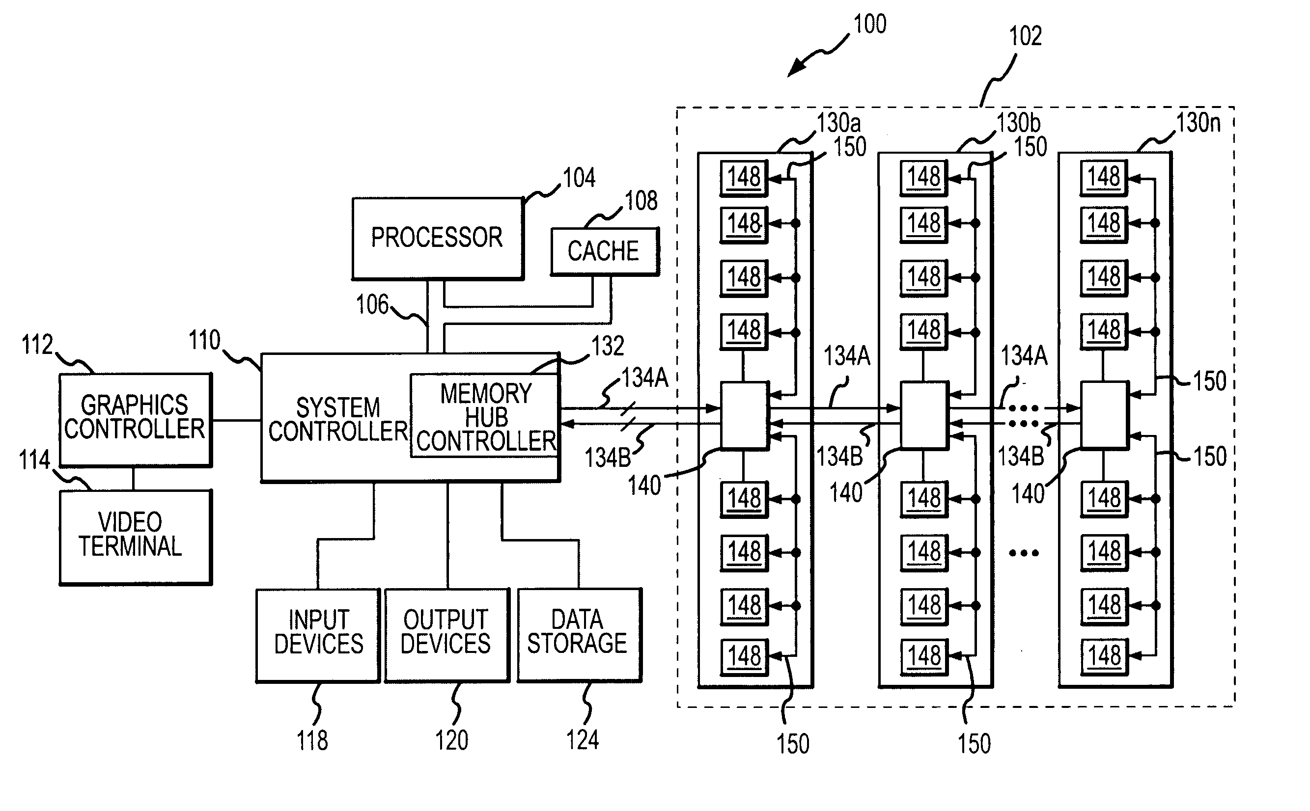
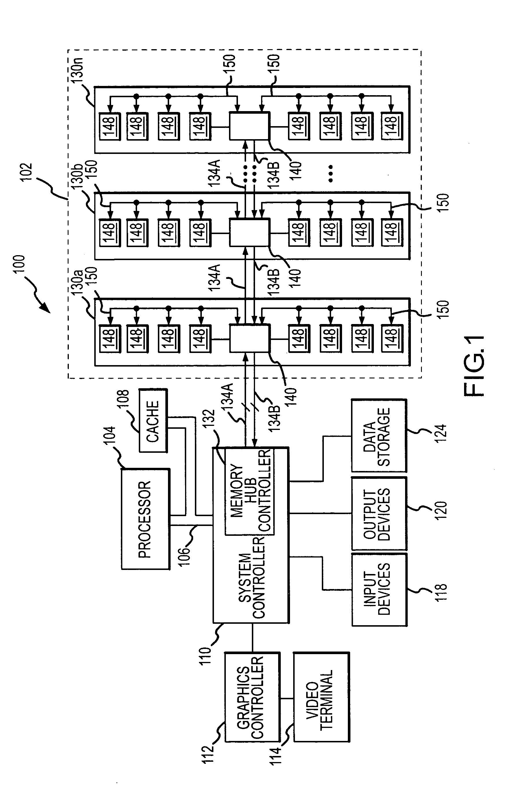
[0014] A computer system 100 according to one example of the present invention is shown in FIG. 1. The computer system 100 includes a system memory 102 having a memory hub architecture including a plurality of memory modules 130, each memory module including a corresponding memory hub 140. Each of the memory hubs 140 arbitrates between memory responses from the memory module 130 on which the hub is contained and memory responses from downstream memory modules, and in this way the memory hubs effectively control the latency of respective memory modules in the system memory by controlling how quickly responses are returned to a system controller 110, as will be described in more detail below. In the following description, certain details are set forth to provide a sufficient understanding of the present invention. One skilled in the art will understand, however, that the invention may be practiced without these particular details. In other instances, well-known circuits, control signa...


PUM


Abstract

A memory hub module includes a decoder that receives memory requests determines a memory request identifier associated with each memory request. A packet memory receives memory request identifiers and stores the memory request identifiers. A packet tracker receives remote memory responses and associates each remote memory response with a memory request identifier and removes the memory request identifier from the packet memory. A multiplexor receives remote memory responses and local memory responses. The multiplexor selects an output responsive to a control signal. Arbitration control logic is coupled to the multiplexor and the packet memory and develops the control signal to select a memory response for output.

Description

TECHNICAL FIELD [0001] This invention relates to computer systems, and, more particularly, to a computer system including a system memory having a memory hub architecture. BACKGROUND OF THE INVENTION [0002] Computer systems use memory devices, such as dynamic random access memory (“DRAM”) devices, to store data that are accessed by a processor. These memory devices are normally used as system memory in a computer system. In a typical computer system, the processor communicates with the system memory through a processor bus and a memory controller. The processor issues a memory request, which includes a memory command, such as a read command, and an address designating the location from which data or instructions are to be read. The memory controller uses the command and address to generate appropriate command signals as well as row and column addresses, which are applied to the system memory. In response to the commands and addresses, data are transferred between the system memory a...

Claims


Application Information

Patent Timeline
Patent Type & Authority Applications(United States)
IPC IPC(8): G06F12/00G06F13/16
CPCG06F13/1642G06F12/00G06F13/00
Inventor JEDDELOH, JOSEPH M.
Owner MICRON TECH INC
Why Eureka
Try Eureka