
Multi-fueled internal combustion engine

a technology of internal combustion engine and fuel injection, which is applied in the direction of engines, machines/engines, mechanical equipment, etc., can solve the problems of simultaneous combustion of two cylinders, and achieve the effect of improving engine performance and mitigating disadvantages

Inactive Publication Date: 2005-08-18
TSE KWONG WANG
View PDF4 Cites 13 Cited by
  • Summary
  • Abstract
  • Description
  • Claims
  • Application Information

AI Technical Summary

Benefits of technology

[0005] Hence, it is an object of the present invention to provide an improved internal combustion engine or engine topology to overcome or, at least, mitigate disadvantages, or bring in advantages associated with conventional and non-conventional internal combustion engines. More specifically, it is an object of the present invention to provide an improved internal combustion engine or engine topology which serves to improve engine performance to take more than one fuel, permit easy swap of fuel, and utilize non-flammable liquid or vapor and water as a fuel in an engine operation. As a minimum, it is at least an object of the present invention to provide the public with a choice of a novel internal combustion engine or engine topology to be described hereinafter. SUMMARY OF THE INVENTION
[0007] Preferably, the engine can take two fuels instead of relying on one. The non-regular fuel can be swapped to other fuels easily, as their combustions are not ignited by their sparks, but by simultaneous combustions of the other fuel—the regular fuel.

Problems solved by technology

One cylinder consumes a regular fuel in its four-stroke cycle, but in its combustion process, its explosion generates high heat and pressure to ignite or burn the other fuel in the other cylinder, causing a simultaneous combustion of two cylinders.

Method used


Image

  • Multi-fueled internal combustion engine
  • Multi-fueled internal combustion engine
  • Multi-fueled internal combustion engine

Examples


Embodiment Construction

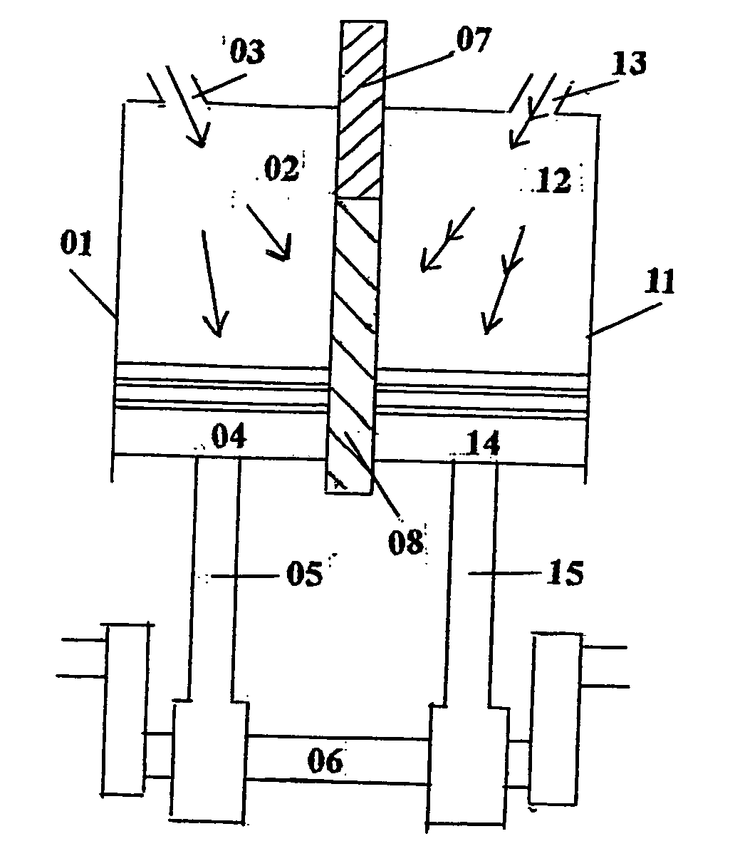
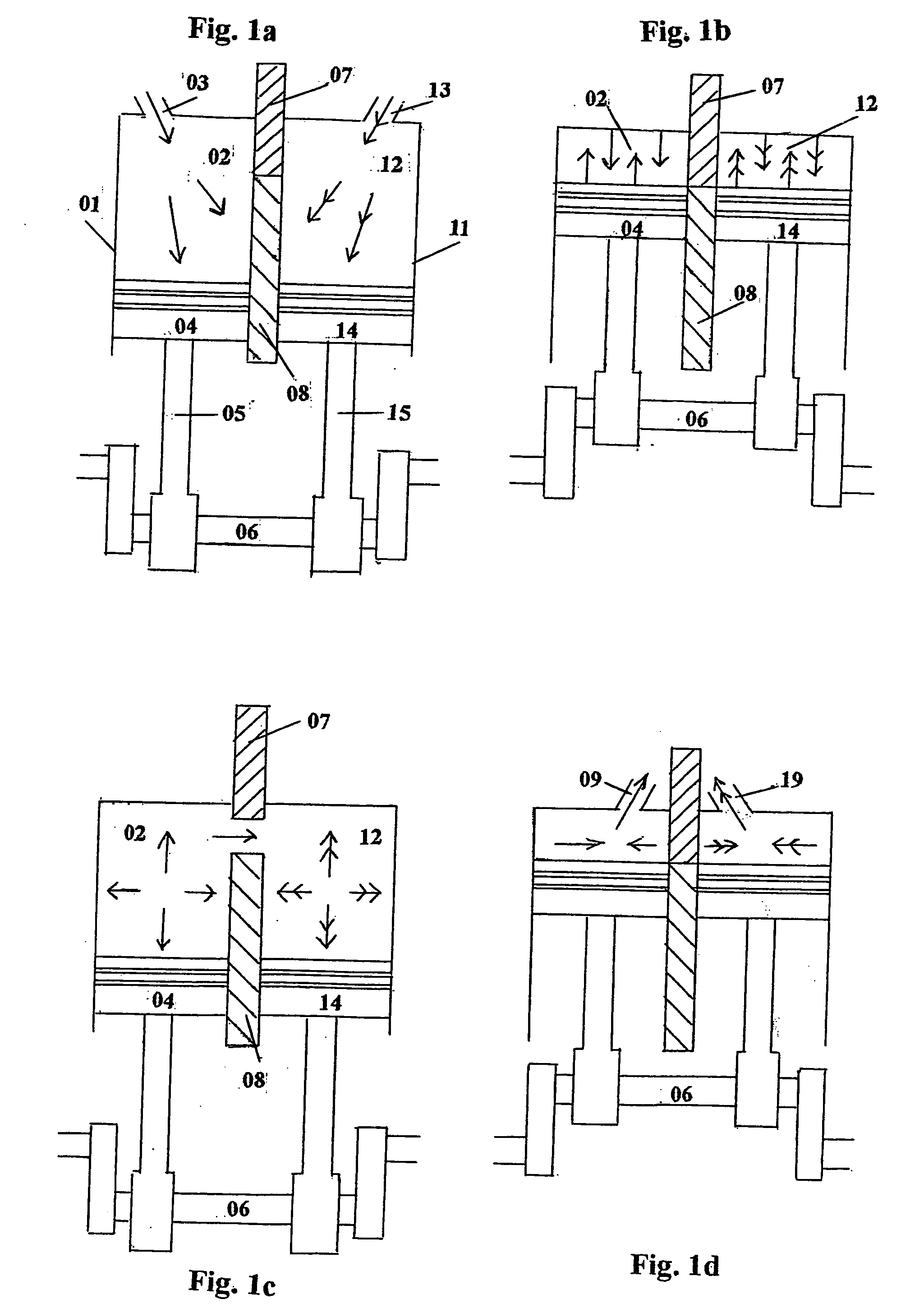
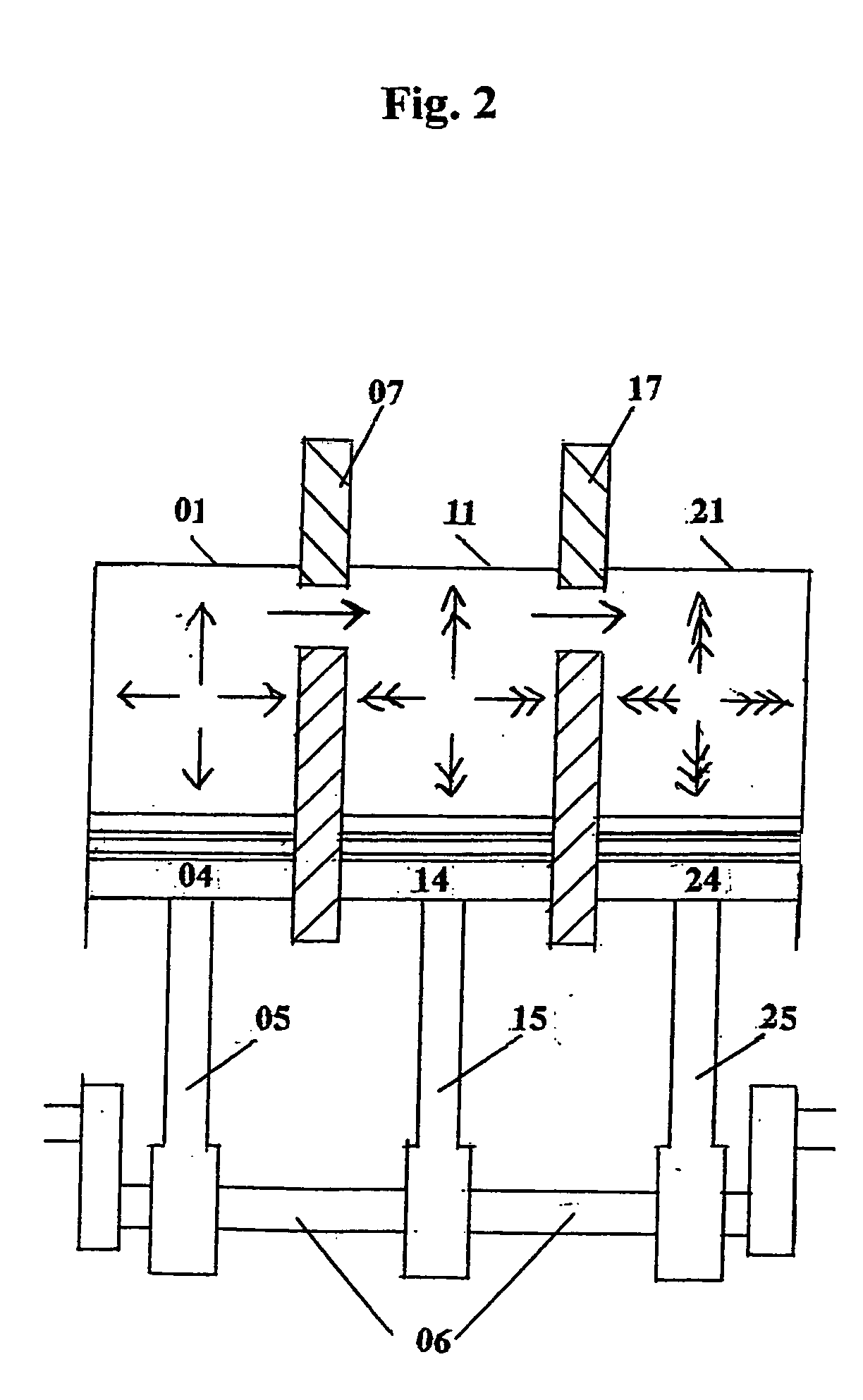
[0021] Referring first to FIGS. 1a to 1d, there are shown simplified sketches of a first preferred embodiment of the present invention comprising a pair of cylinders in a conventional internal combustion engine. The figures show a series of engine operating movements to illustrate the general principles of operation of the present invention. The engine generally includes at least two cylinders, although a plurality of engine cylinders may be, and are generally, connected together to meet with specific power and operation requirements and to fulfill various performance criteria.

[0022] Cylinder (01) generally includes a combustion chamber (02) with a fuel intake aperture (03). The piston member (04) is connected to a connecting rod (05) holding a crankshaft (06) below. The cylinder (01), including the combustion chamber (02), the piston member (04), connecting rod (05) and crankshaft (06), is preferably made of steel, wrought iron or other rigid metal alloys, both ferrous and non-fer...


PUM


Abstract

An internal combustion engine including at least two engine cylinders, and each cylinder can process its own four-stroke cycle of fuel intake, compression, combustion and exhaustion with an open / shut device in between two adjacent cylinders. Fuels in different cylinders or different parts of a cylinder combust together as the open / shut device is opened at combusting time. Each cylinder is consuming different fuels, non-flammable liquid or gas, and water as a fuel for making use of the high temperature and pressure of the combustion of one fuel to dissociate the other fuel or non-flammable fuel into its original flammable elements by burning and combusting in high temperature and pressure. This engine cylinder configuration substantially increases the utilization of fuel and different kinds of fuels to enhance the advantages on flexible, economical, and environmental considerations.

Description

FIELD OF THE INVENTION [0001] This invention relates to internal combustion engines and, more particularly, to internal combustion engines which consume more than one fuel. More specifically, this invention relates to an internal combustion engine of the four-stroke type with more than one cylinder to consume more than one fuel. BACKGROUND OF THE INVENTION [0002] Internal combustion engines are widely used as power plants for many types of equipment and apparatuses such as automobiles, power generators, pumps, compressors, ships, tractors, machines, and airplanes. In order to supply adequate power and considering economic conditions, many kinds of fuel are consumed in the world such as petroleum, diesel, kerosene, liquefied pressured gas, natural gas, methane, alcohol, plantation oil, hydrogen, oxygen, and engine emission. More specifically, this invention relates to an internal combustion engine having different cylinders to consume different fuels. [0003] In general, an internal c...

Claims


Application Information

Patent Timeline
Patent Type & Authority Applications(United States)
IPC IPC(8): F02B41/02F02B43/10F02B75/02F02B75/18F02D19/06
CPCF02B41/02F02B43/10F02B2075/027Y02T10/36F02D19/0644F02D19/0671Y02T10/32Y02T10/30
Inventor TSE, KWONG WANG
Owner TSE KWONG WANG
Learn More