Method of manufacturing tire component member and pneumatic tire

a technology of component parts and pneumatic tires, which is applied in the direction of transportation and packaging, chemistry apparatuses and processes, and other domestic objects, can solve the problems of difficult to form reliable butt joints, difficult to utilize strength, and difficult to form annular structures having the circumference necessary, etc., and achieve the effect of no

Inactive Publication Date: 2005-08-18
BRIDGESTONE CORP
View PDF7 Cites 4 Cited by
  • Summary
  • Abstract
  • Description
  • Claims
  • Application Information

AI Technical Summary

Benefits of technology

[0004] The present invention has been made in view of the foregoing circumstances and it is therefore an object of the present invention to provide a tire component fabricating method capable of

Problems solved by technology

However, the formation of a reliable butt joint is difficult because the corresponding edges of the strips are irregular and the butt joint often includes air.
Consequently, it is difficult to utilize the strength of tire cords when plies are extended

Method used


Image

  • Method of manufacturing tire component member and pneumatic tire
  • Method of manufacturing tire component member and pneumatic tire
  • Method of manufacturing tire component member and pneumatic tire

Examples


Embodiment Construction

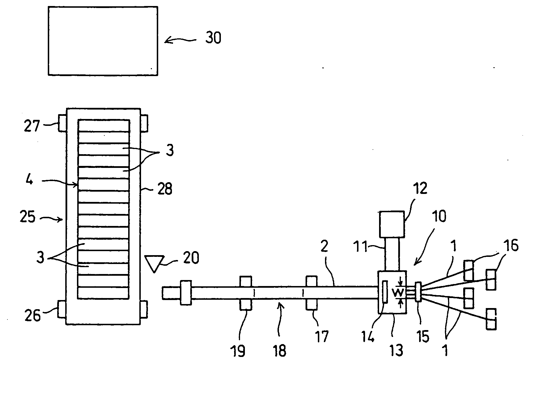
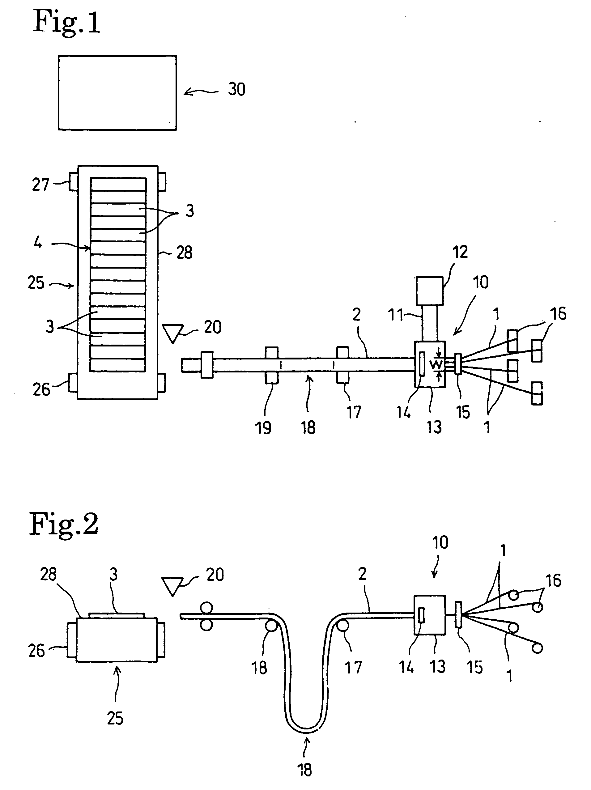
[0023] A preferred embodiment of the present invention will be described with reference to FIGS. 1 to 7.

[0024] The first embodiment of the present invention is a ply forming method of forming a ply, namely, a tire component. FIGS. 1 and 2 shows, in schematic views, a ply fabricating system for carrying out the ply forming method in the first embodiment.

[0025] An extruder 10 has a cylinder 11 internally provided with a screw, and a hopper 12 connected to the cylinder 11 to feed a material into the cylinder 11.

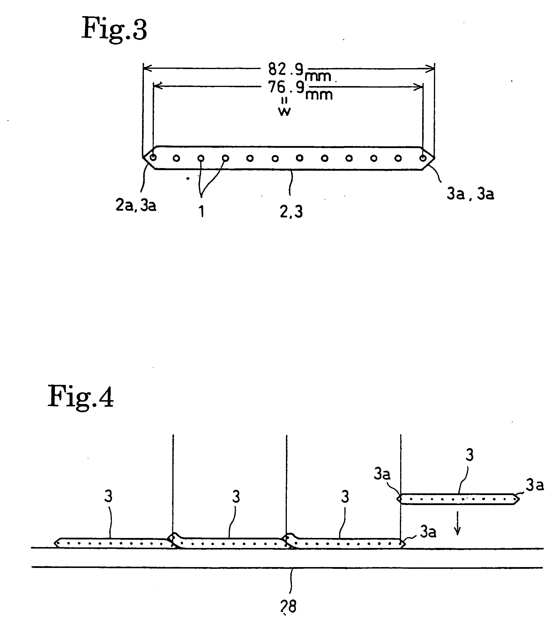
[0026] The material loaded into the hopper 12 is a ply-forming rubber material or the like. The rotating screw kneads the ply-forming rubber material fed into the cylinder 11 and forces the kneaded ply-forming rubber material through a discharge end of the cylinder 11 into a die 14 of a predetermined shape held in an insulation head 13.

[0027] An inserter 15 is disposed behind the die 14 held in the insulator head 13 of the extruder 10. A plurality of reels 16 are disposed be...


PUM

PropertyMeasurementUnit
Lengthaaaaaaaaaa
Thicknessaaaaaaaaaa
Diameteraaaaaaaaaa

Abstract

A tire component is fabricated by the steps of forming a narrow belt by arranging a plurality of cords and embedding the cords in a rubber layer, cutting the belt into strips of a predetermined length, and successively arranging and joining a necessary number of the strips such that edge parts of adjacent strips overlap each other with the outermost cord in the edge part of one of the adjacent strips overlying the outermost cord in the edge part of the other strip. The strips can be surely joined without requiring advanced techniques, without wasting materials and without increasing weight. Thus a desired annular tire component can be accurately formed in a desired circumference. The cords are arranged in each strip in a width equal to a length shorter than a length equal to an integral division of the predetermined circumference of a tire by a length corresponding to an increase in the diameter of the tire component. A tire component of a predetermined circumference can be accurately formed by increasing the diameter of an annular ply fabricated by successively joining an integral number of the strips such that the edge parts of the adjacent strips overlap each other with the outermost cord in the edge part of one of the adjacent strips superposed on the outermost cord in the edge part of the other strip. A pneumatic tire including the thus formed carcass ply thus fabricated has an improved quality.

Description

TECHNICAL FIELD [0001] The present invention relates to a tire component fabricating method of fabricating a component of a tire by successively connecting strips formed by embedding cords in a rubber layer, and a pneumatic tire. BACKGROUND ART [0002] Various previously proposed tire component fabricating methods is intended to form a tire component by joining strips in a butt joint in which the strips are fastened edge to edge. [0003] However, the formation of a reliable butt joint is difficult because the corresponding edges of the strips are irregular and the butt joint often includes air. Consequently, it is difficult to utilize the strength of tire cords when plies are extended, it is difficult to form an annular structure having a necessary circumference, advanced techniques are required, and those previously proposed tire component fabricating method are difficult to carry out even though expensive equipment is necessary. DISCLOSURE OF THE INVENTION [0004] The present inventi...

Claims


Application Information

Patent Timeline
IPC IPC(8): B29D30/38B29D30/42B60C9/04
CPCB29D30/38B29D30/42B29D2030/381Y10S156/906Y10T152/10855Y10T156/1079Y10T156/1075B60C9/04
Inventor SUDA, NOBUYUKIKUBOTA, AKIRA
Owner BRIDGESTONE CORP
Why Eureka
Try Eureka