Low energy vacuum distillation method and apparatus

a vacuum distillation and low energy technology, applied in vacuum distillation separation, vessel construction, separation processes, etc., can solve the problems of limited commercial application, high energy requirements for this system, and limited use of specialized situations, so as to achieve maintenance free and low initial cost

Inactive Publication Date: 2005-08-18
SMART VCR PARTNERSHIP
View PDF26 Cites 5 Cited by
  • Summary
  • Abstract
  • Description
  • Claims
  • Application Information

AI Technical Summary

Benefits of technology

[0007] The present invention is directed toward a still useful as a desalinator which is extremely simple so as to be low in initial cost and maintenance free, and to a condenser employing similar features useful to condense the vapor output of the still of the present invention or other stills.

Problems solved by technology

Because of the complexity and high power requirements of these systems they have had only limited commercial application.
The energy requirements for this system are high and its complexity limits its use to specialized situations.

Method used


Image

  • Low energy vacuum distillation method and apparatus
  • Low energy vacuum distillation method and apparatus
  • Low energy vacuum distillation method and apparatus

Examples


Embodiment Construction

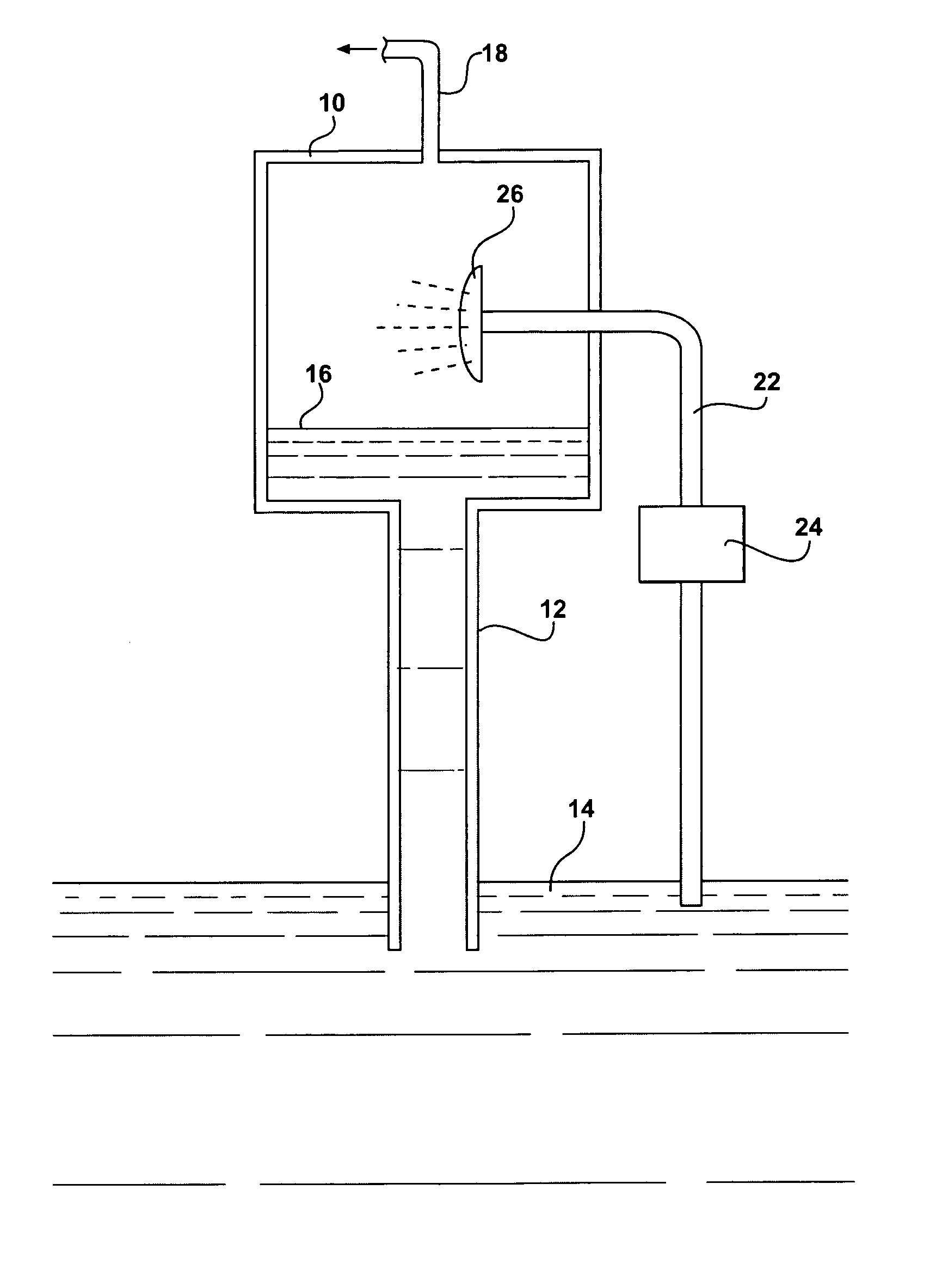
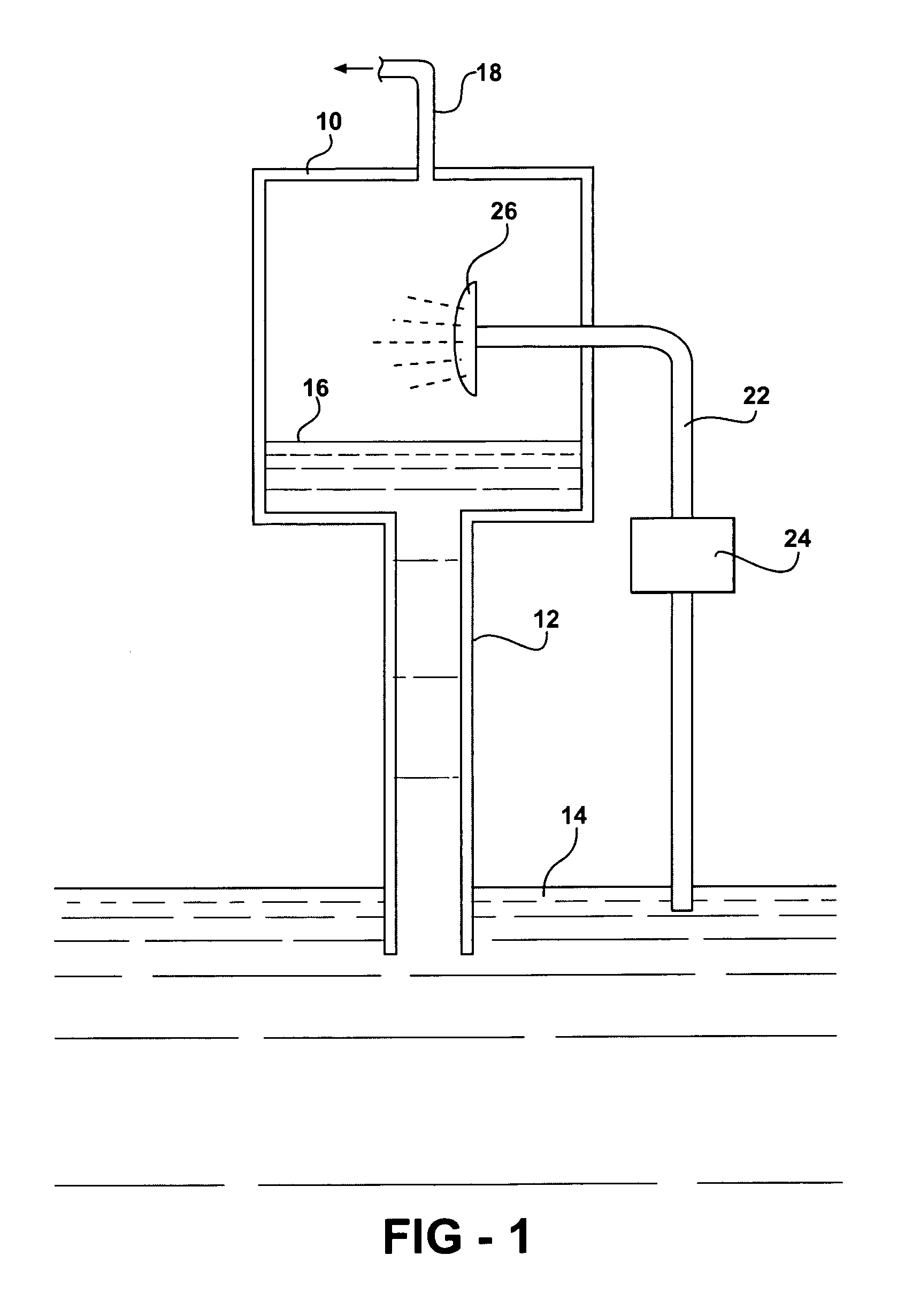
[0015] A preferred embodiment of the invention is schematically illustrated in FIG. 1. The system employs a chamber 10, which is generally sealed and has its lower end connected to an exit pipe 12 which in turn has its lower end disposed in a body of water to be purified 14, preferably seawater or brine, hereinafter termed “source water”. The height of the water column in pipe 12 is such that the surface 16 of the water level within the chamber 10 is at the maximum height that can be supported by the atmospheric pressure on the lower end of the conduit 12 less the pressure within the chamber 10, typically approximately 10 meters. As a result, the volume in the chamber 10 above the water surface 16 is substantially evacuated to a subatmospheric pressure (a “Torricelli vacuum”) and filled with water vapor at a vapor pressure corresponding to the temperature of the water in the chamber 10. The water vapor drawn out of the chamber 10 through conduit 18 represents the distilled output of...


PUM

PropertyMeasurementUnit
heightaaaaaaaaaa
temperatureaaaaaaaaaa
heightaaaaaaaaaa

Abstract

A sub-atmospheric pressure desalinating still employs a closed top, open bottom pipe filled with source water to be distilled, such as seawater, having a height greater than the height of a column of seawater that can be supported by the pressure at the bottom of the tank so that a subatmospheric pressure volume is formed at the top. Water from the source is also pumped into the subatmospheric volume and passed through an evaporator which enlarges its surface volume. A small percentage of the water is vaporized and the balance is cooled to provide the heat of vaporization and falls into the top of the seawater column, creating a downward flow. The vapor is drawn from the vacuum and condensed, preferably in a second subatmospheric volume above a column of fresh water.

Description

RELATED APPLICATIONS [0001] This application is a continuation-in-part of U.S. patent application Ser. No. 10 / 665,457 filed Sep. 19, 2003, which claims priority of U.S. Provisional Patent Application Ser. No. 60 / 412,230 filed Sep. 20, 2002, and U.S. Provisional Patent Application Ser. No. 60 / 498,083 filed Aug. 26, 2003.BACKGROUND OF THE INVENTION [0002] 1. Field of the Invention [0003] This invention relates to a system for distilling seawater or polluted water to produce fresh water. [0004] 2. Background Art [0005] A number of devices and methods have been utilized to purify seawater and brackish water to produce water of lower salinity for irrigation or drinking purposes. Because of the complexity and high power requirements of these systems they have had only limited commercial application. [0006] U.S. Pat. No. 6,436,242 discloses a water distiller using a sub-atmospheric boiler which employs a vacuum pump to reduce the pressure at the top of a tank below that of the atmosphere. ...

Claims


Application Information

Patent Timeline
Patent Type & Authority Applications(United States)
IPC IPC(8): B01D1/16B01D1/28B01D3/10C02F1/04
CPCB01D1/0088B01D1/16B01D1/28C02F1/12C02F1/04C02F1/046C02F1/06B01D3/10Y10S203/11Y02A20/124
Inventor LEVINE, MICHAEL R.
Owner SMART VCR PARTNERSHIP
Why Eureka
Try Eureka