Radar detection method and apparatus

a detection method and apparatus technology, applied in the direction of reradiation, pedestrian/occupant safety arrangement, instruments, etc., can solve the problems of degrading the view through the mirror, difficulty in seeing objects in the side blind spots of the automobile, accidents often occur,

Inactive Publication Date: 2005-08-18
VALEO RADAR SYST
View PDF7 Cites 51 Cited by
  • Summary
  • Abstract
  • Description
  • Claims
  • Application Information

AI Technical Summary

Problems solved by technology

A continuing safety concern in the operation of automobiles is the difficulty in seeing objects in the side blind spots of the automobile.
Accidents often occur when an automobile impacts another vehicle in its blind spot when changing lanes.
Also, the view through mirrors degrades during conditions of rain, snow, or darkness.

Method used


Image

  • Radar detection method and apparatus
  • Radar detection method and apparatus
  • Radar detection method and apparatus

Examples


Embodiment Construction

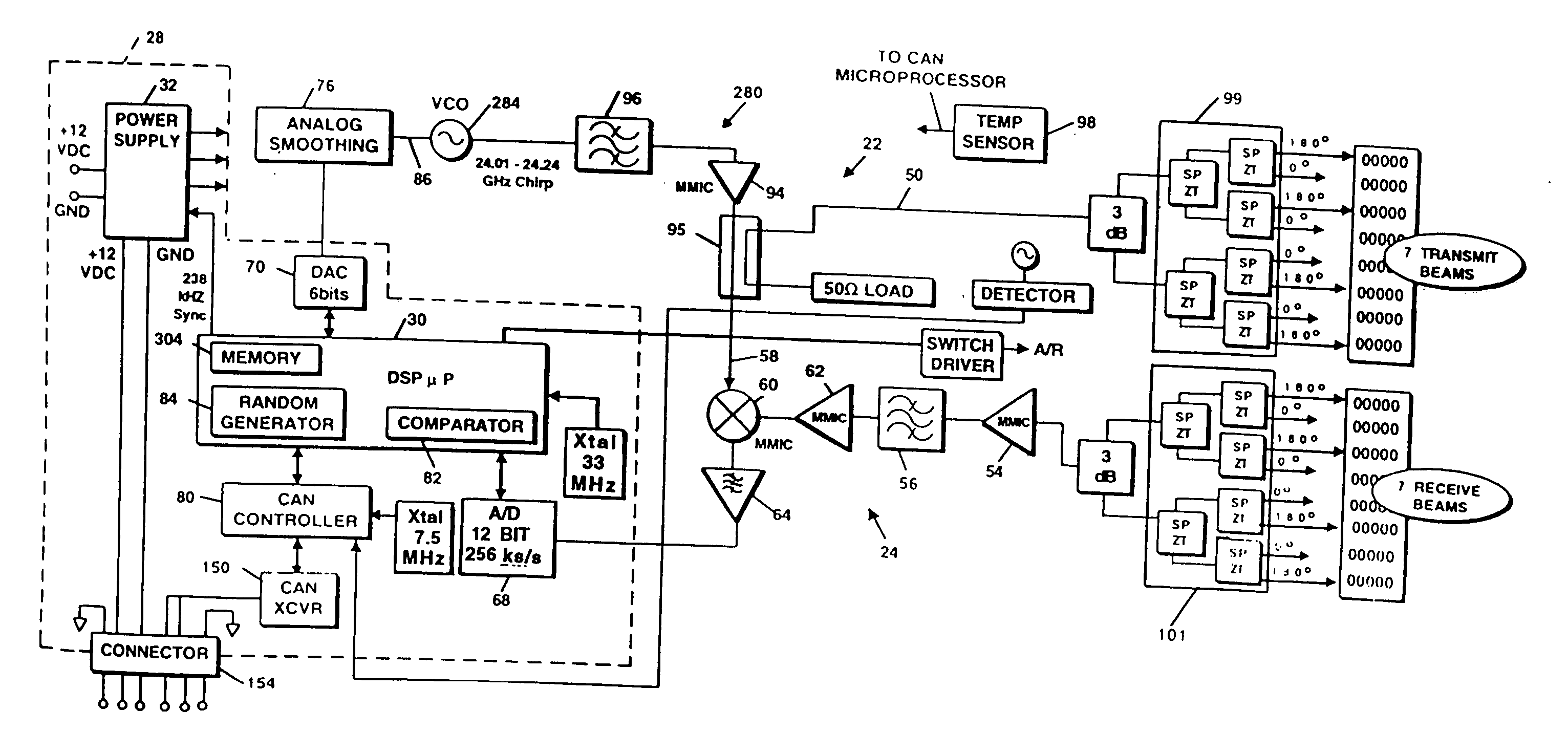
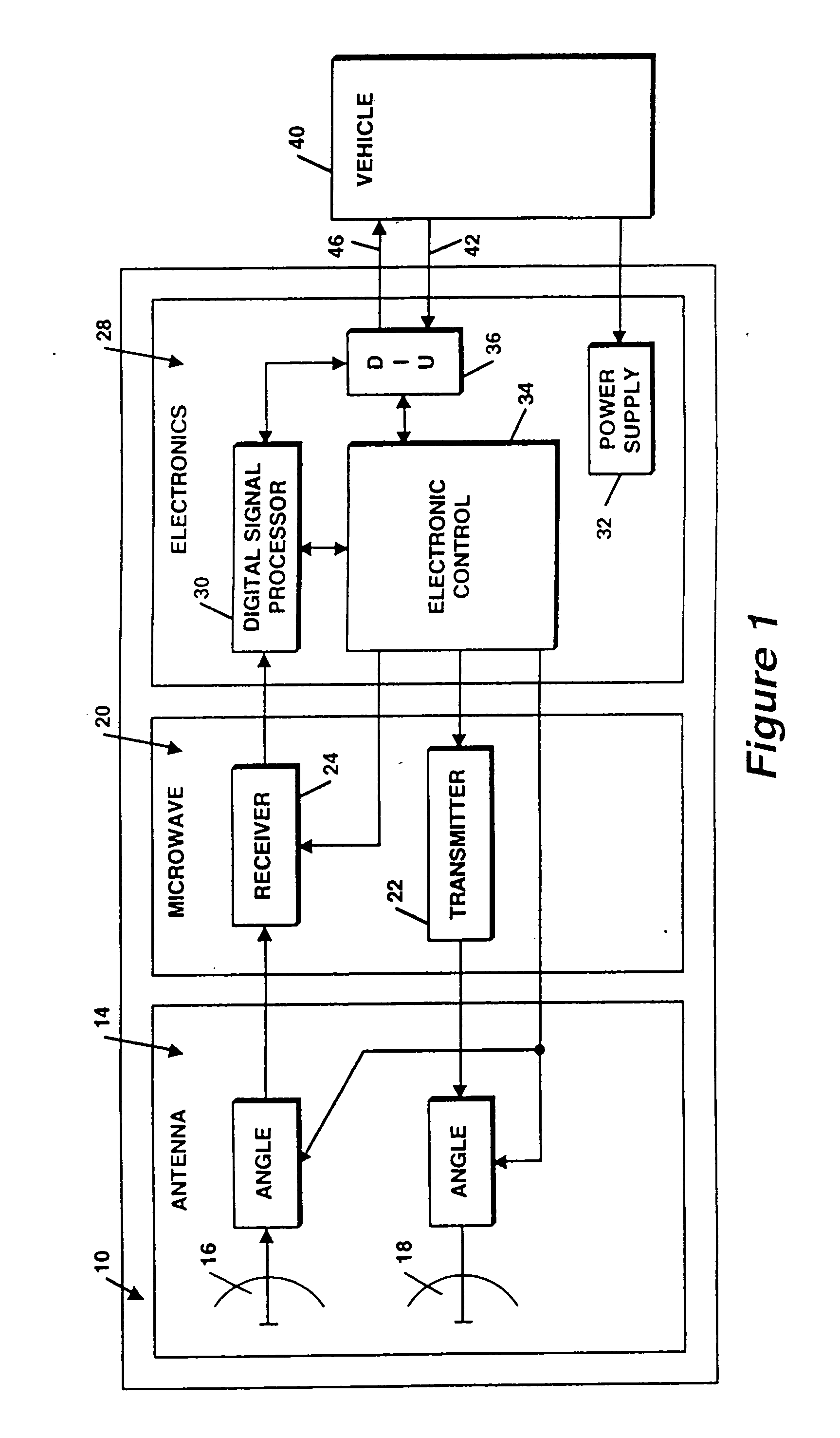
[0030] Referring to FIG. 1, a radar system 10 includes an antenna portion 14, a microwave portion 20 having both a transmitter 22 and a receiver 24, and an electronics portion 28 containing a digital signal processor (DSP) 30, a power supply 32, control circuits 34 and a digital interface unit (DIU) 36. The transmitter 22 includes a digital ramp signal generator for generating a control signal for a voltage controlled oscillator (VCO), as will be described.

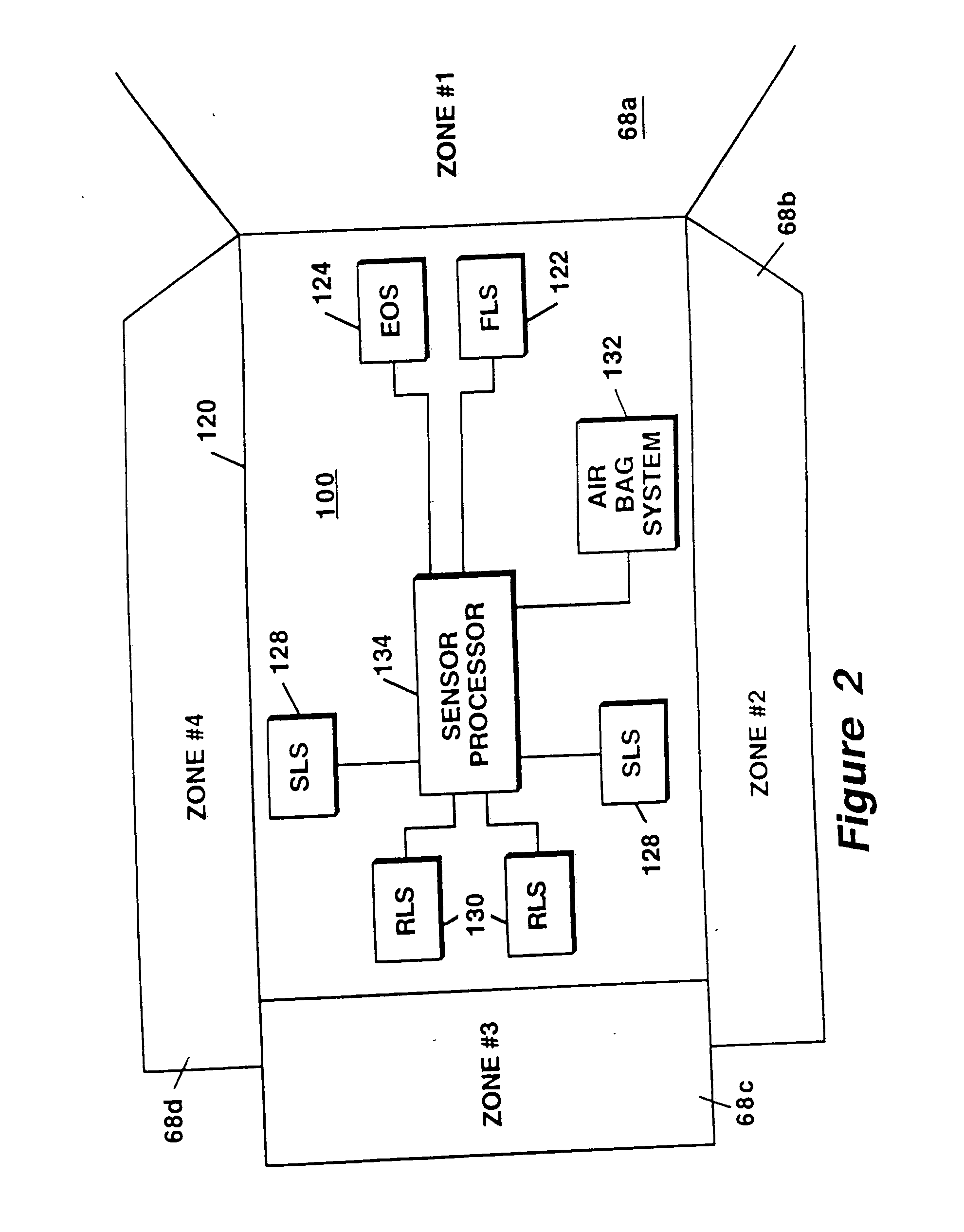
[0031] The radar system 10 utilizes radar technology to detect one or more objects, or targets in the field of view of the system 10 and may be used in various applications. In the illustrative embodiment, the radar system 10 is a module of an automotive radar system (FIG. 2) and, in particular, is a side object detection (SOD) module or system adapted for mounting on an automobile or other vehicle 40 for the purpose of detecting objects, including but not limited to other vehicles, trees, signs, pedestrians, and other objects wh...


PUM


Abstract

A radar system and method use a radar FMCW chirp having variable chirp characteristics.

Description

CROSS-REFERENCE TO RELATED APPLICATIONS [0001] This application is a Continuation Application of U.S. patent application Ser. No. 10 / 886,969 filed on Jul. 8, 2004, which is a Continuation Application of U.S. patent application Ser. No. 10 / 229,256 filed on Aug. 27, 2002, which is a Divisional Application of U.S. patent application Ser. No. 09 / 930,869 filed on Aug. 16, 2001 entitled “Radar Detection Method and Apparatus,” which claims the benefit of U.S. Patent Application No. 60 / 226,160 filed on Aug. 16, 2000 under 35 U.S.C. §119(e), which applications are each hereby incorporated herein by reference in their entirety.STATEMENTS REGARDING FEDERALLY SPONSORED RESEARCH [0002] Not applicable. FIELD OF THE INVENTION [0003] This invention relates generally to vehicle radar systems and more particularly to a radar system to detect other vehicles and objects in close proximity to the vehicle. BACKGROUND OF THE INVENTION [0004] As is known in the art, radar systems have been developed for va...

Claims


Application Information

Patent Timeline
Patent Type & Authority Applications(United States)
IPC IPC(8): B60R21/00B60K31/00B60Q1/26B60Q1/52G01S7/02G01S7/03G01S7/26G01S7/285G01S7/288G01S7/35G01S7/40G01S13/02G01S13/04G01S13/28G01S13/34G01S13/48G01S13/58G01S13/72G01S13/87G01S13/89G01S13/931H01Q1/32H01Q1/38H01Q1/42H01Q3/24H01Q3/26H01Q3/40H01Q13/06H01Q13/10H01Q21/00H01Q21/06H01Q25/00H03F1/30H03H7/01H03H21/00
CPCB60K31/0008G01S13/346B60T2201/081B60T2201/088B60W2530/10B60W2550/304G01S7/023G01S7/032G01S7/038G01S7/06G01S7/288G01S7/354G01S7/4004G01S7/4008G01S7/4021G01S13/04G01S13/282G01S13/343G01S13/48G01S13/584G01S13/726G01S13/87G01S13/931G01S2007/356G01S2013/0245G01S2013/9321G01S2013/9332G01S2013/9375G01S2013/9378G01S2013/9385G01S2013/9389H01Q1/3233H01Q1/3258H01Q1/3283H01Q1/38H01Q1/42H01Q3/24H01Q3/40H01Q13/10H01Q13/18H01Q21/0043H01Q21/0075H01Q21/0087H01Q21/065H01Q25/00B60Q9/008G01S7/352B60T2201/08B60W2554/803G01S2013/9315G01S2013/93271G01S2013/93272G01S2013/93274G01S2013/93275G01S13/003G01S13/865G01S13/878G01S13/42B60W2554/4043G01S7/356G01S7/0232
Inventor WOODINGTON, WALTER GORDONDELCHECCOLO, MICHAEL JOSEPHPLEVA, JOSEPH S.RUSSELL, MARK E.VAN REES, H. BARTELD
Owner VALEO RADAR SYST
Why Eureka
Try Eureka