Fringe field switching liquid crystal display

a liquid crystal display and filter field technology, applied in optics, instruments, constructions, etc., can solve the problems of deteriorating the characteristics of manufactured goods, inferior afterimages,

Active Publication Date: 2005-08-18
BOE HYDIS TECH
View PDF5 Cites 14 Cited by
  • Summary
  • Abstract
  • Description
  • Claims
  • Application Information

AI Technical Summary

Benefits of technology

[0008] Accordingly, the present invention has been made to solve the above-mentioned problems occurring in the prior art, and an object of the present invention is to provide a fringe field switching liquid crystal display, in which a black matrix has low resistance so that an electric field and pixels are formed by using a conductive material in order to operate peripheral liquid crystal molecules without creating disclination lines in the vicinity of a wedge section, and in which, a common electric field is applied to a black matrix region so as to form the electric field between the black matrix and a pixel electrode, so that liquid crystal molecules aligned between a data line and the pixel electrode are operated, thereby improving the liquid crystal polarization efficiency of a pixel electrode.

Problems solved by technology

According to the conventional FFS-LCD having the above construction, since an overlapped region between electrodes is very wide, layers such as insulation layers may be deteriorated if the conventional FFS-LCD operates for a long period of time, causing inferior afterimages.
Therefore, transmittance is reduced due to such a relationship between the pixel wedge and the black matrix 106, and luminance is not uniform due to an alternation operation between the pixel wedge and the black matrix 106, thereby deteriorating the characteristics of manufactured goods.

Method used


Image

  • Fringe field switching liquid crystal display
  • Fringe field switching liquid crystal display
  • Fringe field switching liquid crystal display

Examples


first embodiment

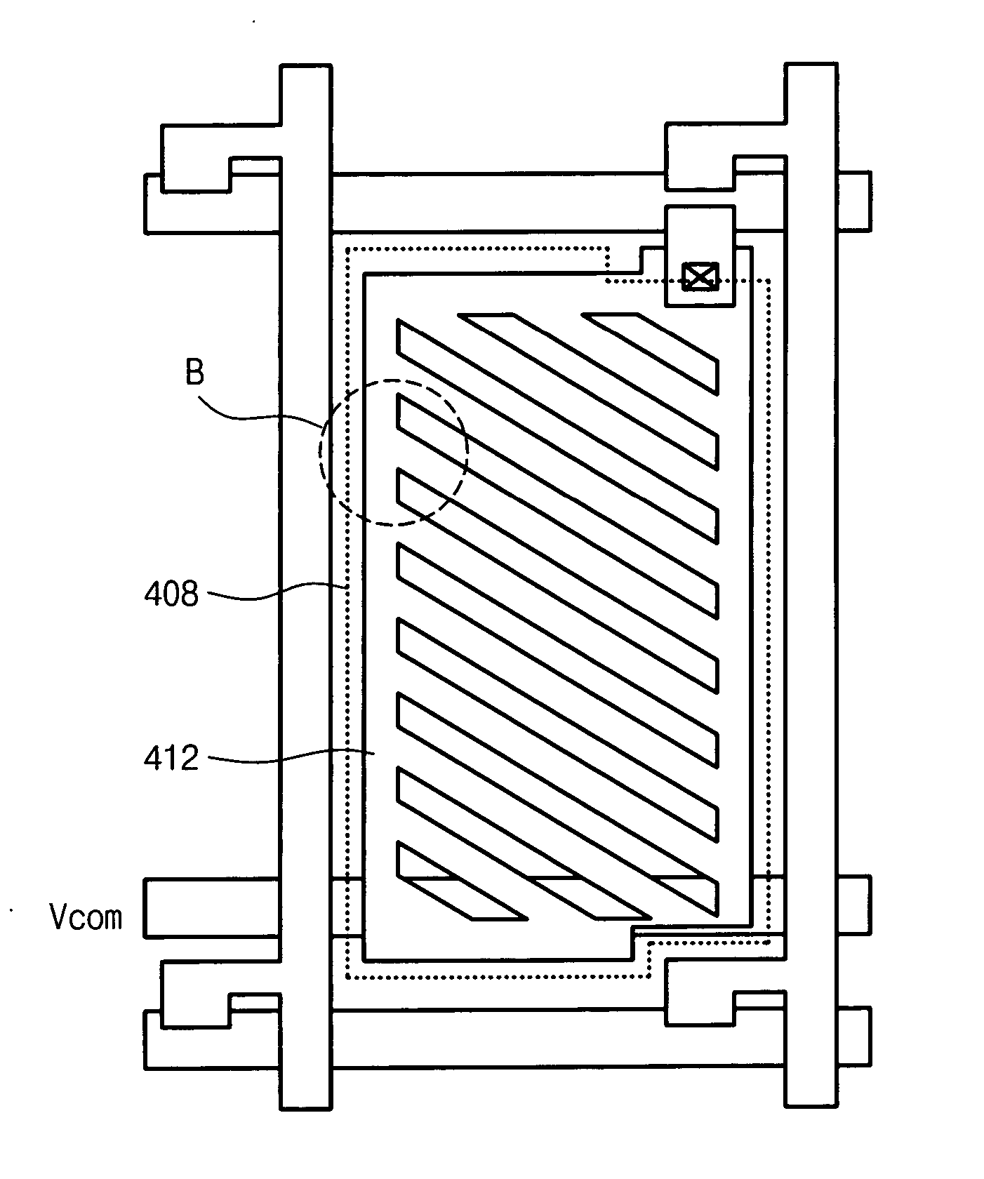
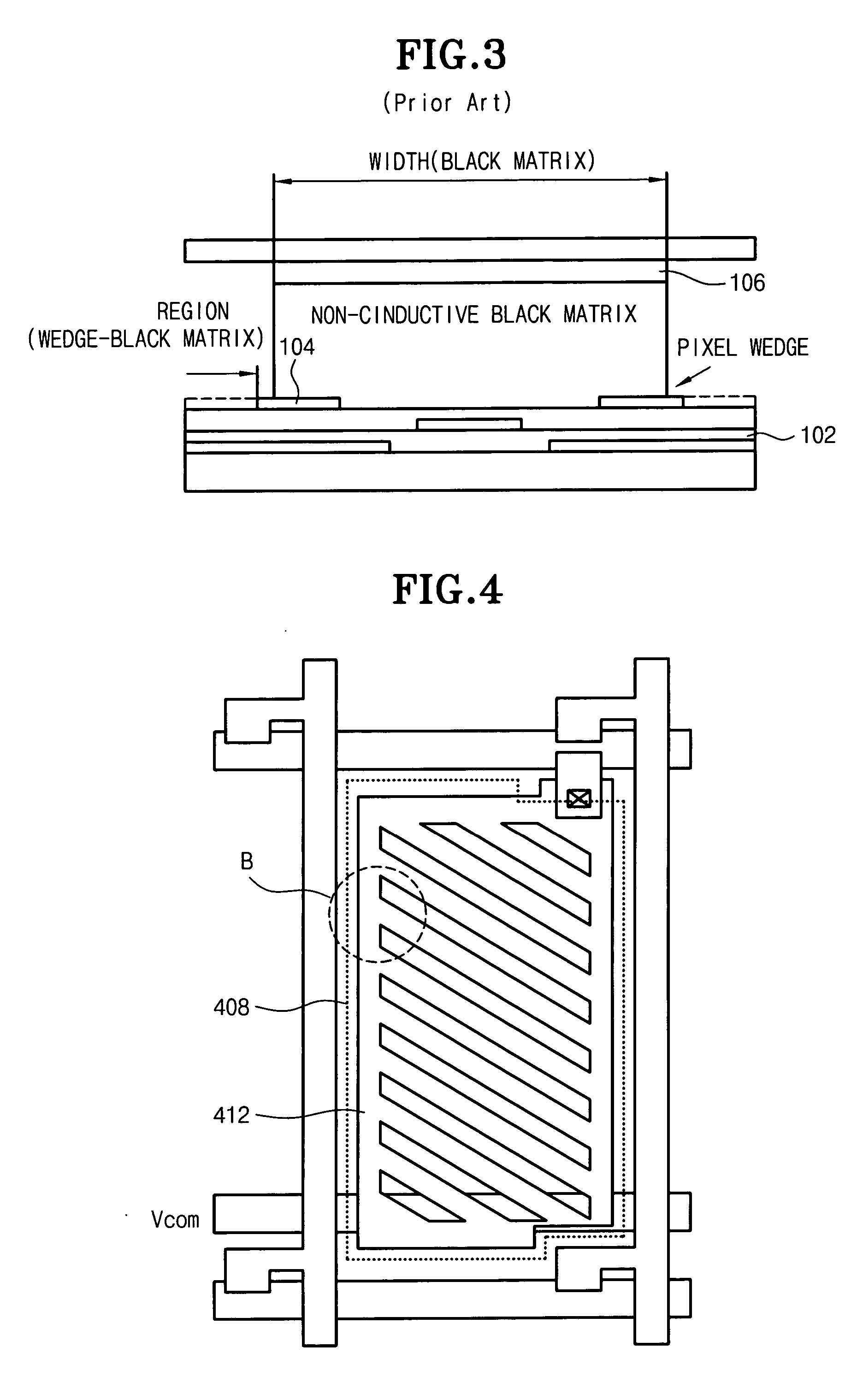
[0020]FIG. 4 is a plan view illustrating a fringe field switching liquid crystal display (hereinafter, referred to as ‘FFS-LCD’) according to the present invention. In addition, FIG. 5 is an enlarged view of a region ‘B’ shown in FIG. 4, and FIG. 6 is a sectional view illustrating the FFS-LCD shown in FIG. 4.

[0021] According to the first embodiment of the present invention, the FFS-LCD includes an upper substrate 402, a low substrate 404, a conductive black matrix 406, a common electrode 408, a gate insulation layer 410, and a pixel electrode 412.

[0022] The upper substrate 402 and the lower substrate 404 are arranged with a space between them. The conductive black matrix 406 is formed on a upper surface of the upper substrate 402 except for a predetermined region of the upper substrate 402. The common electrode 408 is formed on an upper surface of the lower substrate 404. The gate insulation layer 410 is formed on an upper surface of the common electrode 408.

[0023] The pixel elect...

second embodiment

[0028]FIG. 7 is a view illustrating a black matrix 702, a common electrode 704, and a pixel electrode 706 according to the present invention. The pixel electrode 706 includes a fringe portion 708 of a saw-tooth shape.

[0029] When the common electrode 704 is located within the black matrix 702, it is preferred that a ratio of ‘x’:‘y’:‘z’ is 1:1:1. Herein, ‘x’ represents a distance between the black matrix 702 and the pixel electrode 706, ‘y’ represents a length of the saw-tooth shaped fringe portion 708 of the pixel electrode 706, and ‘z’ represents a length of the pixel electrode 706 except for the fringe portion 708 thereof.

third embodiment

[0030]FIG. 8 is a view illustrating a black matrix 802, a common electrode 804, and a pixel electrode 806 according to the present invention. The black matrix 802 includes a fringe portion 808 of a saw-tooth shape. In addition, the pixel electrode 806 includes a fringe portion 810 of a saw-tooth shape.

[0031] The common electrode 804 is located out of the black matrix 802. In this case, it is preferred that a ratio of ‘x’:‘y’:‘z’ is 1:2:2. Herein, ‘x’ represents a distance between the black matrix 802 and the pixel electrode 806, ‘y’ represents a length of the saw-tooth shaped fringe portion 810 of the pixel electrode 806, and ‘z’ represents a length of the pixel electrode 806 except for the fringe portion 810 thereof.

[0032] As described above, there are provided constructions of FFS-LCDs, which have higher transmittances, as compared with the conventional art, by modifying a shape of a black matrix and / or a pixel wedge section. That is, it is possible to improve the transmittance b...


PUM

PropertyMeasurementUnit
conductiveaaaaaaaaaa
electric fieldaaaaaaaaaa
lengthaaaaaaaaaa

Abstract

Disclosed is a fringe field switching liquid crystal display, which prevents disclination lines from being created at a wedge section and improves liquid crystal polarization efficiency of a pixel electrode. The fringe field switching liquid crystal display comprises upper and lower substrates arranged while forming a space between them, a conductive black matrix formed on a lower surface of the upper substrate, a common electrode formed on an upper surface of the lower substrate, a gate insulation layer formed on an upper surface of the common electrode, and a pixel electrode formed on an upper surface of the gate insulation layer. Herein, the pixel electrode forms an electric field and includes a fringe portion having a saw-tooth shape, which forms one of 1-domain and 2-domain among the pixel electrode, the conductive black matrix, and the common electrode.

Description

BACKGROUND OF THE INVENTION [0001] 1. Field of the invention [0002] The present invention relates to a liquid crystal display, and more particularly to a fringe field switching liquid crystal display (hereinafter, simply referred to as ‘FFS-LCD’) in which the polarization efficiency of liquid crystal is improved by using an electric field applied to a black matrix, a common electrode, and a pixel electrode. [0003] 2. Description of the Prior Art [0004]FIG. 1 is a plan view illustrating a conventional FFS-LCD. In addition, FIG. 2 is an enlarged view of an ‘A’ portion shown in FIG. 1, and FIG. 3 is a sectional view illustrating the conventional FFS-LCD shown in FIG. 1. [0005] According to the conventional FFS-LCD, as shown in FIGS. 1 to 3, a second ITO electrode 104 overlapped on a first ITO electrode 102 is fabricated in a comb-teeth pattern, and the alignment of liquid crystal is aligned at 0°. Therefore, when liquid crystal molecules are twisted by an electric field, upper liquid c...

Claims


Application Information

Patent Timeline
Patent Type & Authority Applications(United States)
IPC IPC(8): G02F1/1337G02F1/133G02F1/1335G02F1/1343G02F1/136
CPCG02F1/133512G02F2201/122G02F2001/134372G02F1/134363G02F1/134372E02D29/14
Inventor LEE, KYUNG HAAN, CHI WOOK
Owner BOE HYDIS TECH
Why Eureka
Try Eureka