Charging and discharging control circuit, and charging type power supply device

a control circuit and power supply device technology, applied in secondary battery servicing/maintenance, emergency protection arrangements for limiting excess voltage/current, safety/protection circuits, etc., can solve the problems of secondary battery becoming an overcharge state or overdischarge, risk of ignition or explosion of the battery, etc., to increase the test time efficiency

Active Publication Date: 2005-08-18
ABLIC INC
View PDF3 Cites 10 Cited by
  • Summary
  • Abstract
  • Description
  • Claims
  • Application Information

AI Technical Summary

Benefits of technology

[0018] Therefore an object of the present invention is to reduce mass production costs by achieving a test function controlled from an external portion, without adding external portion terminals, and further, by providing a plurality of delay time modes.
[0020] Further, provided is accelerating means for shortening the delay time of a delay circuit in the testing state by increasing the oscillation frequency of an oscillator circuit that configures the delay circuit.
[0022] According to the present invention, switching between the normal state and the testing state can be performed by applying a voltage from an external portion to the output terminal of the control signal of the charging and discharging control circuit. In addition, switching the delay time according to the presence or absence of a fuse in the testing state becomes possible. Consequently, the charging and discharging control circuit of the present invention achieves a testing function without adding terminals, and achieves increased testing time efficiency by providing a plurality of delay times in the testing state.

Problems solved by technology

However, since a secondary battery is repeatedly charged and discharged, there is a high probability that the secondary battery will become an overcharge state or an overdischarge state.
Thus, there is a risk of ignition or explosion of the battery.
On the other hand, if the secondary battery becomes the overdischarge state, the electrolyte is decomposed to deteriorate the characteristics of the battery.
However, the delay time causes extra time to be required to test the charging and discharging control circuit during an inspection process.
Problems like those described below exist with the conventional technique described above.
Accordingly, adding external portion terminals in order to control the detection delay time during testing invites cost increases, and this is not received well by the marketplace.
Achieving this type of control function by using a small number of external portion terminals is therefore a large problem.
In particular, the circuit structure becomes complex with the technique described above when a plurality of levels of over-current detection are required, and there is a problem in that it is difficult to ensure stable operation.
This is a serious problem that invites increased testing costs during a manufacturing process.

Method used


Image

  • Charging and discharging control circuit, and charging type power supply device
  • Charging and discharging control circuit, and charging type power supply device
  • Charging and discharging control circuit, and charging type power supply device

Examples


Embodiment Construction

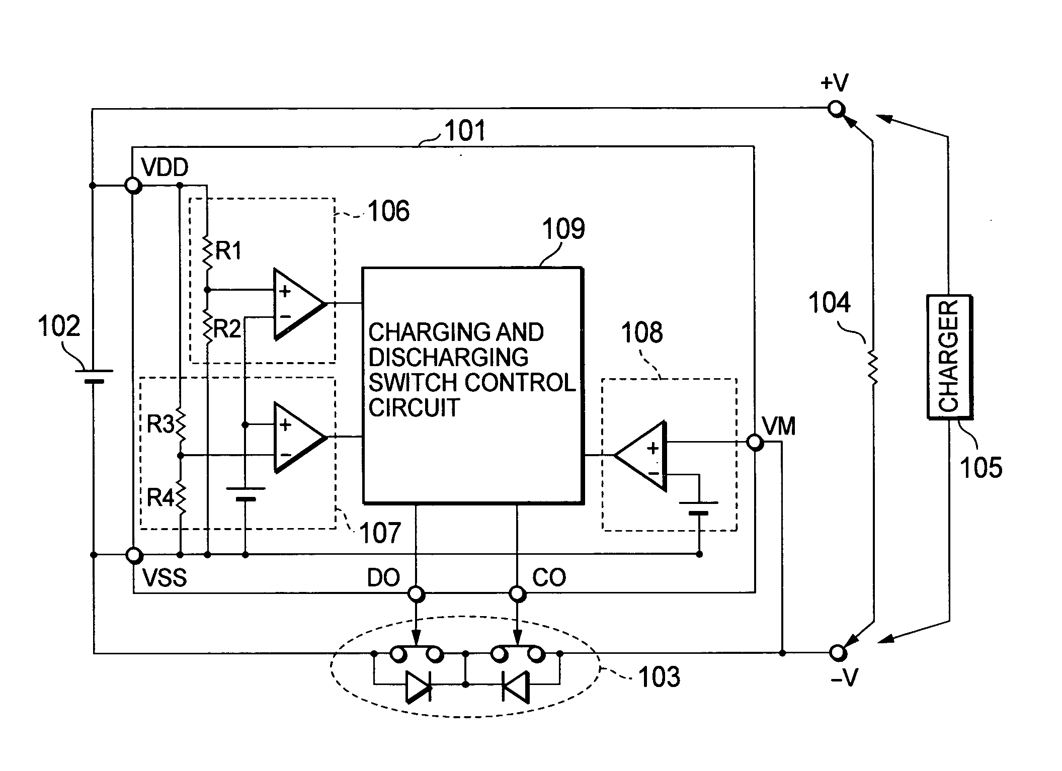
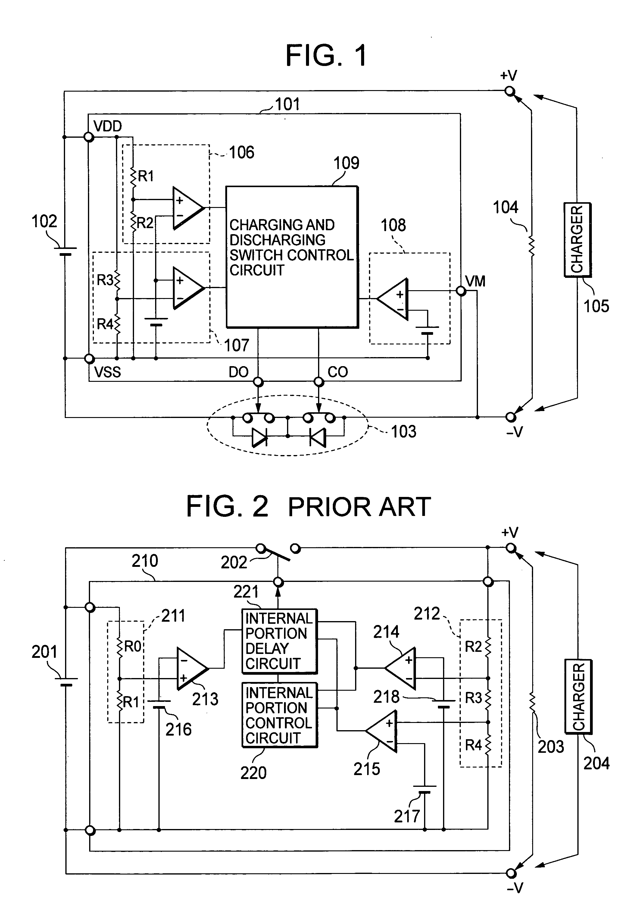
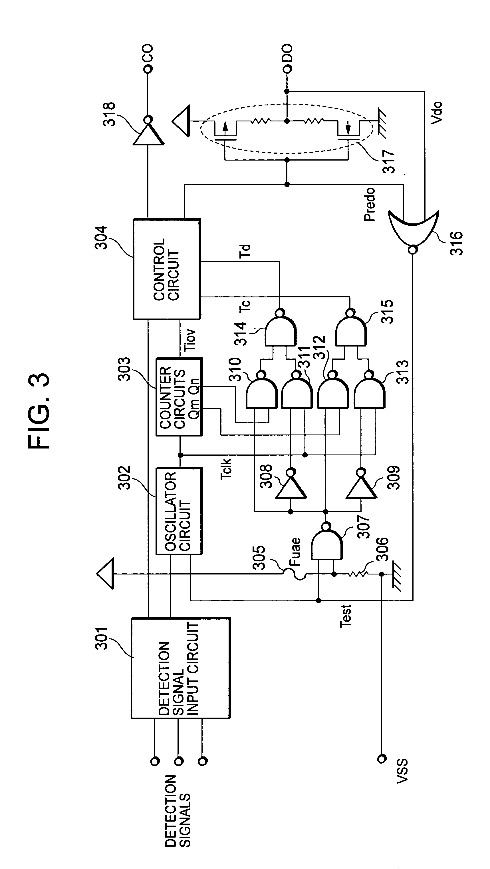
[0029] Embodiments of the present invention are explained in detail below with reference to the drawings. FIG. 1 is a block diagram of a charging and discharging control circuit 101, one embodiment of the present invention. A charging and discharging switch control circuit 109 including a delay circuit determines a delay time for the charging and discharging control circuit. FIG. 3 shows details of the charging and discharging switch control circuit 109 including the delay circuit of FIG. 1. FIG. 4 shows a configuration of a charging type power supply device that utilizes a charging and discharging control circuit 401 proposed by the present invention.

[0030] The charging and discharging control circuit 401 of FIG. 4 includes a positive electrode connection terminal VDD and a negative electrode connection terminal VSS of a secondary battery 402, an over-current detection terminal VM, a charging control output terminal CO, and a discharging control output terminal DO. The charging an...


PUM

PropertyMeasurementUnit
timeaaaaaaaaaa
timeaaaaaaaaaa
delay timeaaaaaaaaaa

Abstract

A charging and discharging control circuit capable of switching between a normal operating state and a testing state without adding an external portion terminal, and capable of switching a delay time in the testing state, is provided. Switching between the normal operating state and the testing state can be performed by the presence or absence of a voltage applied from an external portion to an output terminal of a control signal of the charging and discharging control circuit used in a secondary battery. In addition, a fuse is provided, making it possible to switch the delay time in the testing state.

Description

BACKGROUND OF THE INVENTION [0001] 1. Field of the Invention [0002] The present invention relates to a charging and discharging control circuit and a charging type power supply device of a secondary battery. In particular, the present invention relates to a method of switching into and out of a testing state for evaluating the characteristics of the charging and discharging control circuit. [0003] 2. Description of the Related Art [0004] The features of a lithium ion secondary battery which has greatly contributed to the popularization of mobile devices typified by a mobile telephone and a PHS are its small size, lightweight, and large capacity. Those features have led to realization of long time driving and lightness of the mobile devices. However, since a secondary battery is repeatedly charged and discharged, there is a high probability that the secondary battery will become an overcharge state or an overdischarge state. If the secondary battery becomes the overcharge state, the ...

Claims


Application Information

Patent Timeline
Patent Type & Authority Applications(United States)
IPC IPC(8): H01M10/44H02H7/00H02J7/00H02J7/04
CPCH02J7/0047H02J7/0031Y02E60/10H02J7/04H01M10/44
Inventor ZHANG, WEI
Owner ABLIC INC
Why Eureka
Try Eureka