More compact and higher reliability power source system

a power source system and compact technology, applied in the direction of dc-ac conversion without reversal, dc source parallel operation, power supply for data processing, etc., can solve the problems of reducing the service life of the device, affecting the reliability of the device, and the failure of one of the components of the device, so as to reduce the ripple, reduce the electrical discharge, and reduce the ripple

Inactive Publication Date: 2005-08-18
DIVERSIFIED TECH INC
View PDF10 Cites 46 Cited by
  • Summary
  • Abstract
  • Description
  • Claims
  • Application Information

AI Technical Summary

Benefits of technology

[0022] In one embodiment, the switch may include a diode. The power supply may include a plurality of power supply modules each including a plurality of DC / DC converters and a controller. Each DC / DC converter may be configured as a buck converter with a switch triggered by the controller to modulate the DC / DC converter. Each DC / DC converter may include an inverter, a transformer, and a rectifier in which the inverter is cycled by the controller to modulate the DC / DC converter. The controller may be configured to modulate each DC / DC converter using modulation. The controller may be configured to stagger the timing of the switch of each DC / DC converter to reduce ripple on the low voltage DC bus. The controller may be responsive to a fault signal input and programmed to open the switch of each DC / DC converter in response to a fault signal. The controller may be configured to stagger the timing of the inverter of each DC / DC converter to reduce ripple on the low voltage DC bus. The controller may be responsive to a fault signal input and programmed to open the inverter of each DC / DC converter in response to a fault signal. Each power supply module may include a fuse between the plurality of DC / DC converters and the low voltage DC bus designed to fail at a current level greater than the rated current output of the power supply module. The controller may be configured to determine a desired output voltage based on the current output by the power supply module. The controller may include a switching voltage regulator configured to compare a desired system output voltage with the voltage level output by the power supply module and to adjust the voltage output of each DC / DC converter such that the output of the power supply module approximately equals the desired system output voltage. The switching voltage regulator may adjust the voltage output by each of the DC / DC converters utilizing modulation. The controller of each of the plurality of power supply modules may utilize pseudo-impedance to provide autonomous load sharing of the plurality of power supply modules. The low voltage output on the low voltage DC bus may be in the range of about 6V DC to 100V DC. The low voltage output on the low voltage DC bus voltage may be about 48V DC. The controller may be further configured to output an error signal in response to a fault signal. The controller may further include a fault determination circuit for generating the fault signal. Each of the plurality of power supply modules may include a cooling system. The fault detection circuit may generate a fault signal when a power supply module exceeds a predetermined temperature. The buck converter may include an input capacitor, an output capacitor, an inductor, and the switch. The ratio of the high voltage on the high voltage DC bus to the low voltage on the low voltage DC bus may be in the range 1.1:1 to about 1000:1. The ratio of the high voltage on the high voltage DC bus to the low voltage on the low voltage DC bus may be about 10:1. The ratio of the high voltage on the high voltage DC bus to the low voltage on the low voltage DC bus may be about 2:1. The power supply may be housed in a cabinet. Each of the plurality of power supply modules may be configured as a removable drawer. The removable drawers may be disposed in the cabinet. Each removable drawer may include a plurality of different length connectors that electrically connect the number of DC / DC converters of the power supply module to the high voltage DC bus at different times to reduce electrical discharge. Each of the connectors may include a resistive material therein for reducing electrical discharge when connecting the power supply module to the high voltage DC bus. Each removable drawer may include an auxiliary contact connected by a separate auxiliary resistor or spark-suppressing impedance network for further reducing electrical discharge. The removable drawers may be able to be removed, replaced, or added while the system is running. Each drawer may include a number of cooling fans and exhaust ports for cooling the power supply modules. The components of each of the plurality of power supply modules may be arranged to maximize cooling efficiency. The computing loads may be chosen from the group consisting of: a telecommunications system, a data communication system, a computer system, and computer peripherals. The power supply may include a redundant number of power supply modules.

Problems solved by technology

However, conventional static transfer switches and transformer / rectifier devices typically provide no redundancy capabilities.
Hence, failure of one of the components of these devices requires shutting the device down to replace the damaged component.
Because the battery system is no longer being charged, it can sustain the system only for a limited number of hours, after which failure of the battery supplied power will result.
Since losses are proportional to current squared times the resistance (I2R), keeping I2R losses down has required conventional battery systems to employ expensive, bulky, and not readily reconfigurable, bus-bar current distribution systems to carry the high current, low voltage DC power close to the point of use.
Prior battery based systems are expensive, massive, inflexible and occupy too much space.
Moreover, the environmental hazards associated with the toxic waste created during battery manufacturing and disposal are increasingly intolerable.
To date, high voltage DC power distribution has been impractical because of the lack of an economical and scalable DC-DC voltage down-converter.
Very large Ultra HVDC converters have been in use for many years, but they require gigantic installations and are completely unsuited to scaling down for the purpose of distributing DC power at common distribution voltages needed for a telecommunications system or a data communication system.

Method used


Image

  • More compact and higher reliability power source system
  • More compact and higher reliability power source system
  • More compact and higher reliability power source system

Examples


Embodiment Construction

[0035] Aside from the preferred embodiment or embodiments disclosed below, this invention is capable of other embodiments and of being practiced or being carried out in various ways. Thus, it is to be understood that the invention is not limited in its application to the details of construction and the arrangements of components set forth in the following description or illustrated in the drawings. If only one embodiment is described herein, the claims hereof are not to be limited to that embodiment. Moreover, the claims hereof are not to be read restrictively unless there is clear and convincing evidence manifesting a certain exclusion, restriction, or disclaimer.

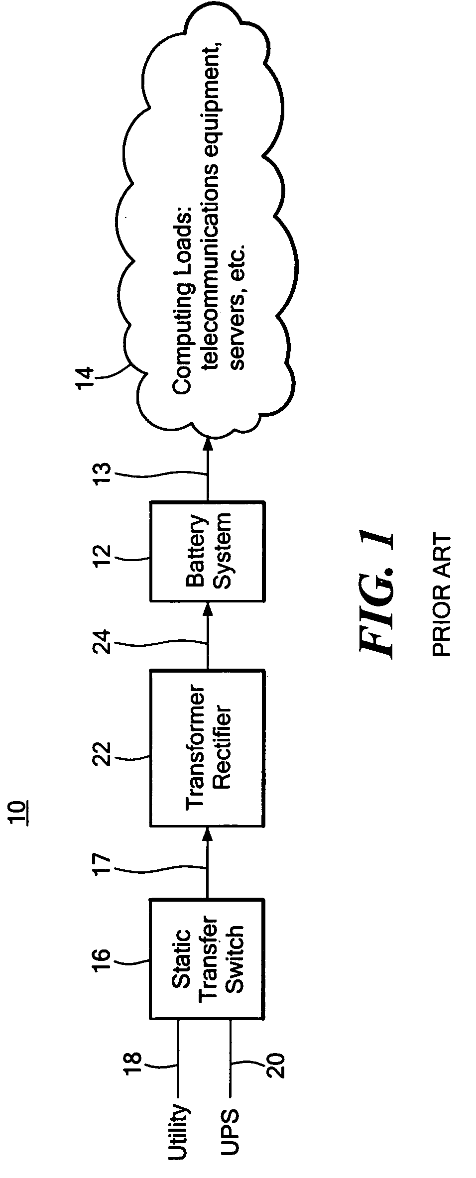
[0036] As discussed in the Background section above, conventional power source system 10, FIG. 1, utilizes large battery system 12 to provide low voltage DC, e.g., 48V DC, to computing loads 14, such as data communications equipment, computer systems, and the like. System 10 typically includes static transfer switch 16 re...


PUM


Abstract

This invention features a more compact and higher reliability power source system for computing loads, the system including a high voltage DC bus connected to a number of DC sources each connected to the high voltage DC bus by a switch configured to deliver to the high voltage DC bus the DC source with the highest DC voltage, a low voltage DC bus connected to the computing loads, and a power supply including a number of DC/DC converters connected in parallel between the high voltage DC bus and the low voltage DC bus, and a controller configured to modulate each DC/DC converter to convert the high voltage on the high voltage DC bus to a low voltage output on the low voltage DC bus.

Description

RELATED APPLICATIONS [0001] This application claims priority of U.S. Provisional Application No. 60 / 545,444 filed Feb. 18, 2004 and U.S. Provisional Application Ser. No. 60 / 545,461 filed Feb. 18, 2004. All of these applications are incorporated by reference herein.FIELD OF THE INVENTION [0002] This invention relates to a compact, higher reliability power source system for supplying low voltage DC power to computing loads from a high voltage DC power source. BACKGROUND OF THE INVENTION [0003] In a typical installation of a telecommunications system, data communications system, computer equipment, servers, and the like, power is almost always supplied by a massive rechargeable storage battery system with sufficient capacity to carry the system through any power outages or interruptions. The battery system is completely clamped at the sum of individual cell voltages and any primary power interruptions are completely bridged. Hence, any powerline-frequency ripple coming from the externa...

Claims


Application Information

Patent Timeline
Patent Type & Authority Applications(United States)
CPCH02J1/10H02J1/001G06F1/26
Inventor GAUDREAU, MARCEL PIERRE JOSEPHDANDRIDGE, PETER ANDREWKEMPKES, MICHAEL ALANCASEY, JEFFREY ALLEN
Owner DIVERSIFIED TECH INC
Why Eureka
Try Eureka