Method of controlling data transmission, radio system, packet control unit, and remote network element

a technology of packet control unit and data transmission, which is applied in the field of controlling data transmission, can solve the problems of reducing the efficiency of data transmission, so as to achieve optimal base station operation and save resources

Inactive Publication Date: 2005-08-18
NOKIA CORP
View PDF13 Cites 45 Cited by
  • Summary
  • Abstract
  • Description
  • Claims
  • Application Information

AI Technical Summary

Benefits of technology

[0018] The embodiments of the invention provide several advantages. The roundtrip times of downlink retransmissions are reduced. The distributed network functionalities are only performed for data block flows requiring it. Thus, the resources of the packet radio system are saved. Also, optimal base station operation is achieved.

Problems solved by technology

When the packet control unit is located apart from a base station, the RLC / MAC retransmissions and uplink sending permission assignments, for example, are not working so optimally as possible because the interface used between the base station and the packet control unit adds delay into the operation.
However, the delays in the “local packet control unit architecture” are minimised and limited mainly by available processing power.
Delays of data transfer in (E)GPRS based networks may be too high for delay sensitive applications like VolP (Voice over IP) and streaming in poor radio conditions.
However, some situations, such as RLC (Radio Link Control) data block retransmission and sending permission assignments to the mobile stations in uplink direction, increase delays and may cause wasting all uplink radio transmitter permissions to some mobile stations.

Method used


Image

  • Method of controlling data transmission, radio system, packet control unit, and remote network element
  • Method of controlling data transmission, radio system, packet control unit, and remote network element
  • Method of controlling data transmission, radio system, packet control unit, and remote network element

Examples


Embodiment Construction

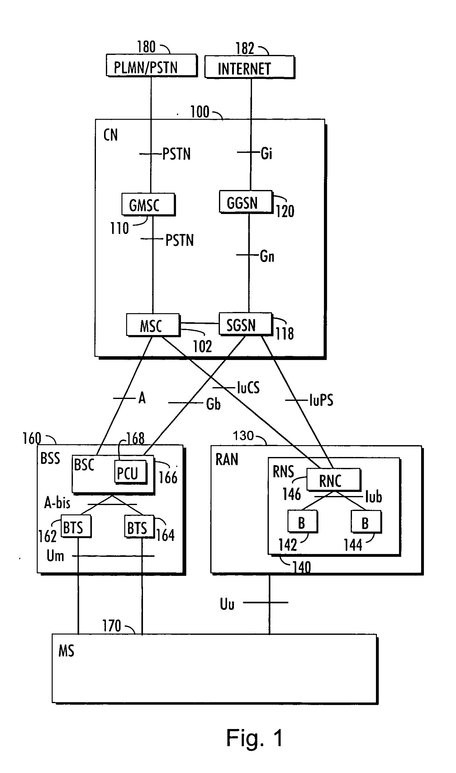
[0024]FIG. 1 is a simplified block diagram, which shows the most important parts of a radio system and the interfaces between them at network-element level. The main parts of a radio system are a core network (CN) 100, a radio access network 130 and user equipment (UE) 170. The radio access network 130 may be implemented by wideband code division multiple access (WCDMA) technology. The structure and functions of the network elements are not described in detail, because they are generally known.

[0025] A mobile services switching center (MSC) 102 is a mobile network element that can be used to serve the connections of both radio access network and a base station system 160. The tasks of the mobile services switching center 102 include: switching, paging, user equipment location registration, handover management, collection of subscriber billing information, encryption parameter management, frequency allocation management, and echo cancellation. The number of mobile services switching...


PUM


Abstract

There is provided a radio system comprising a remote network element, a packet control unit and a mobile station, the radio system being configured to communicate control blocks and data blocks between the mobile station, the packet control unit and the remote network element, the control blocks controlling data transmission in the radio system. The packet control unit is configured to determine which given packet control unit functionalities related to the transmission of given control or data blocks are to be distributed from the packet control unit to a remote net-work element, and to provide to the remote network element control information on which packet control unit functionalities are distributed to the remote network element; and the remote network element is configured to perform the given packet control unit functionalities for given control blocks or data blocks on the basis of the control information received from the packet control unit.

Description

BACKGROUND OF THE INVENTION [0001] 1. Field of the Invention [0002] The invention relates to a method of controlling data transmission in a radio system, to a radio system, to a packet control unit, to a remote network element, to a base transceiver station and to a base station controller. [0003] 2. Description of the Related Art [0004] In known radio systems, a packet control unit may control the communication between mobile stations and the radio system over radio interface. The packet control unit uses an RLC (radio link control) / MAC (medium access control) protocol in the communication between the mobile stations and the network. When the packet control unit is located apart from a base station, the RLC / MAC retransmissions and uplink sending permission assignments, for example, are not working so optimally as possible because the interface used between the base station and the packet control unit adds delay into the operation. [0005] An RLC roundtrip delay, for example, is an i...

Claims


Application Information

Patent Timeline
Patent Type & Authority Applications(United States)
IPC IPC(8): H04L1/00H04L1/16H04L1/18H04L12/56H04W28/04
CPCH04L1/0003H04L1/0009H04L1/1614H04W28/04H04L1/1832H04L2001/0097H04L1/1819H04W28/10
Inventor NIEMELA, KARIFORSSELL, MIKA
Owner NOKIA CORP
Why Eureka
Try Eureka