
ATM cell transfer apparatus with hardware structure for OAM cell generation

a technology of hardware structure and oam cell, which is applied in the field of atm cell transfer apparatus, can solve the problems of difficult processing operation of cpu and oam cell, oam cell of loop back/continuity check is not frequently generated or sent back, and the processing operation of ais/rdi oam cell

Inactive Publication Date: 2005-08-18
JUMIPER NETWORKS INC
View PDF14 Cites 6 Cited by
  • Summary
  • Abstract
  • Description
  • Claims
  • Application Information

AI Technical Summary

Benefits of technology

This solution allows for efficient and timely generation and transfer of OAM cells for multiple F4(VP) and F5(VC) flows, adhering to ITU-T specifications, and correctly notifies the CPU of OAM cell content, enhancing system reliability and performance.

Problems solved by technology

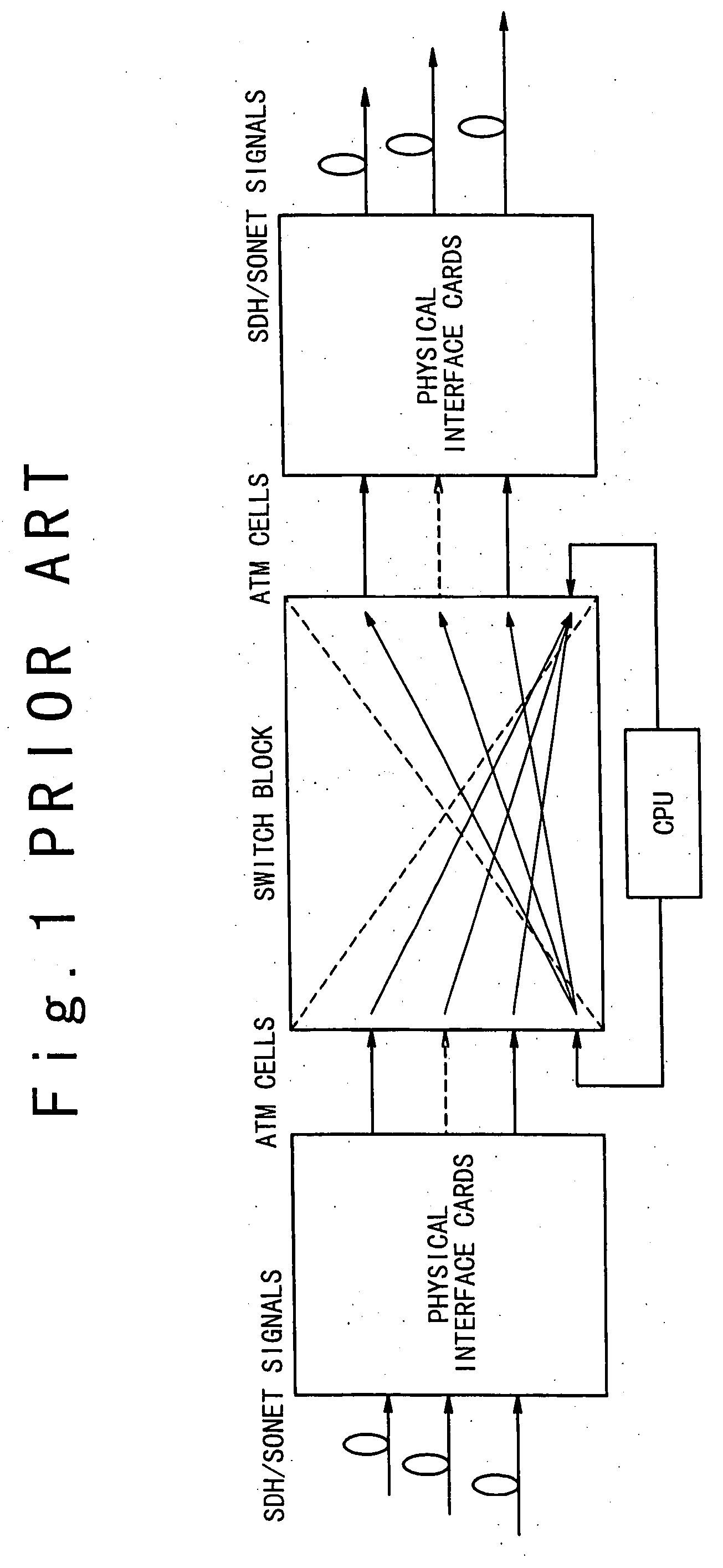
However, it is sometimes difficult that the CPU carries out all of the processing operations of the OAM cells.
As a result, these OAM cells of Loop Back / Continuity Check are not frequently generated or sent back while the actual ATM service operation is carried out.
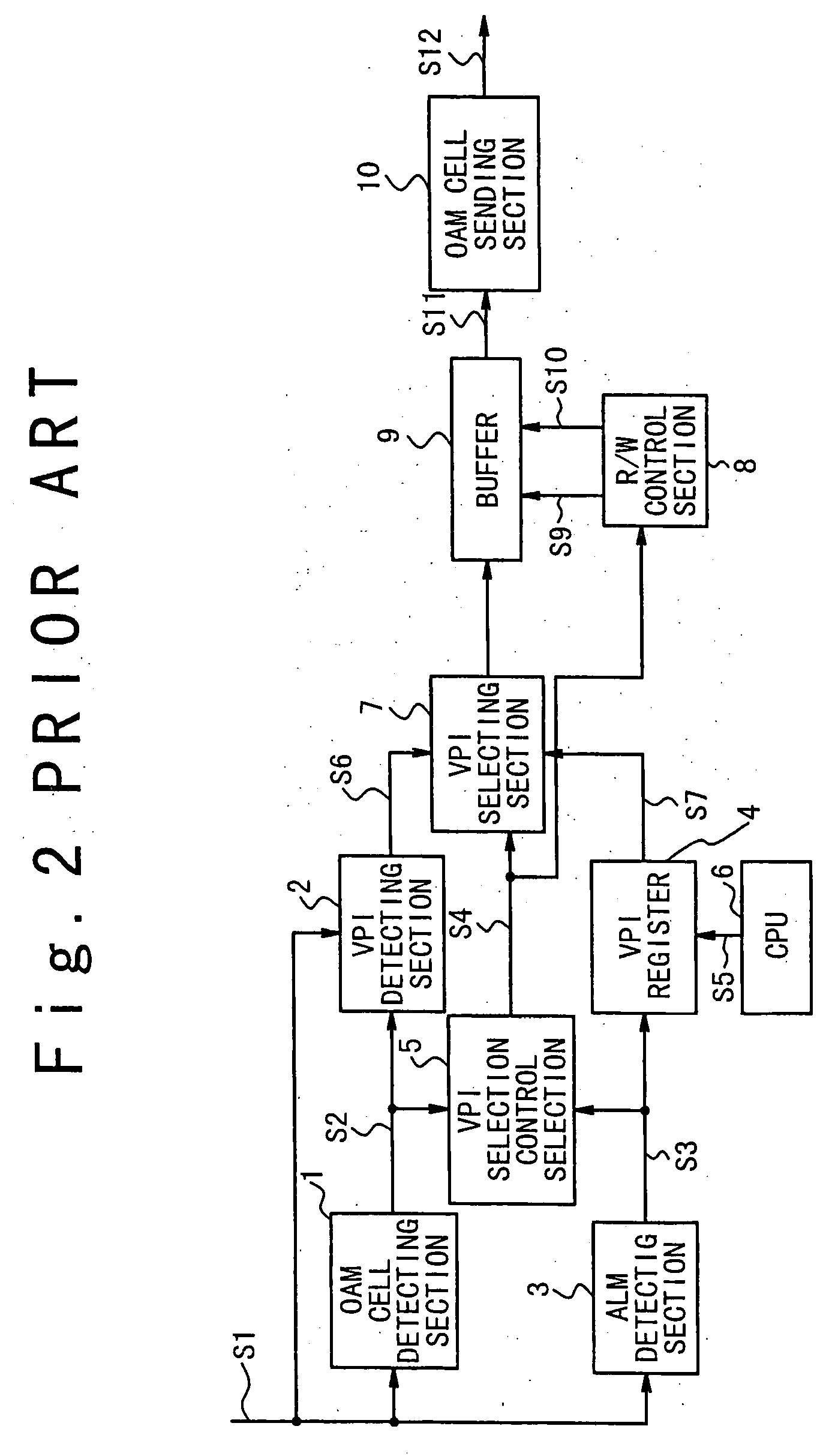
However, as shown in FIG. 14, there is a problem in the processing operation of the AIS / RDI OAM cell.
In the worst case, there is a possibility that this CPU itself may stop the processing operation thereof.
Also, there is another possibilities that a similar unfavorable result may be caused, when a large number of AIS OAM cells are transferred from the counter apparatus in a large number of F4(VP) flows or F5(VC) flows.
In addition, this conventional ATM cell transfer system similarly does not consider the manipulating operation of the OAM cell when the failure occurs on the transfer path.

Method used


Image

  • ATM cell transfer apparatus with hardware structure for OAM cell generation
  • ATM cell transfer apparatus with hardware structure for OAM cell generation
  • ATM cell transfer apparatus with hardware structure for OAM cell generation

Examples


Embodiment Construction

[0083] Hereinafter, an ATM (Asynchronous Transfer Mode) cell transfer apparatus of the present invention will be described below in detail with reference to the attached drawings.

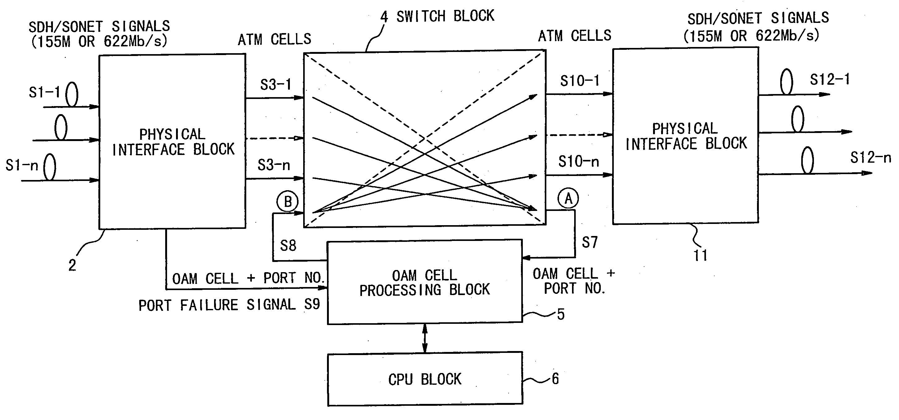
[0084]FIG. 3 shows the structure of the ATM cell transfer apparatus according to the first embodiment of the present invention. Referring to FIG. 3, the ATM cell transfer apparatus in the first embodiment is composed of a physical interface block 2, a switch block 4, an OAM cell processing block 5, a CPU block 6, and a physical interface block 11.

[0085] The physical interface block 2 is connected to a plurality of transfer paths, and receives a plurality of SDH / SONET signals S1-1 to S1-n (n is a natural number) having ATM cells as payloads. The SDH / SONET signal is a standard interface signal between apparatuses and has the basic transfer rate of 155 Mb / s or 622 Mb / s. The physical interface block 2 transfers ATM cells S3-1 to S3-n to corresponding signal ports of the switch block 4. Thus, the overhead of e...


PUM


Abstract

An ATM (asynchronous transfer mode) cell transfer apparatus includes an input interface, a switch block, and an OAM cell processing hardware block having a memory unit. The input interface receives an SDH / SONET signal on each of a plurality of first transfer paths to output an input OAM cell corresponding to the SDH / SONET signal to one of a plurality of input ports of the switch block corresponding to the first transfer path for the SDH / SONET signal to be transferred. The switch block receives the input OAM (operation and maintenance) cell from the corresponding input port as an OAM input port to output to the OAM cell processing hardware block together with a port number of the OAM input port, and receives at least one output OAM cell from the OAM cell processing hardware block to output to at least one of the plurality of output ports based on the received output OAM cell. The OAM cell processing hardware block reads out the at least one output OAM cell corresponding to the input OAM cell from the memory unit based on the input OAM cell and the port number supplied from the switch block, and outputs the at least one output OAM cell to the switch block.

Description

BACKGROUND OF THE INVENTION [0001] 1. Field of the Invention [0002] The present invention generally relates to an ATM (Asynchronous Transfer Mode) cell transfer apparatus. More specifically, the present invention relates to an ATM cell transfer apparatus suitable for transferring an OAM (Operation And Maintenance) cell. [0003] 2. Description of the Related Art [0004] A processing method of an OAM cell executed in an ATM cell transferring operation is defined in the specification I.610 of ITU-T (International Telecommunication Union-Telecommunication Standardization Sector). In this specification, a processing time required to transfer an OAM cell when any failure occurs is also defined. Further, an OAM cell transferring operation in PVC (Permanent Virtual Channel) is defined. [0005] A processing operation of an OAM cell should be carried out as follows in this specification to notify the occurrence of any failure. That is, it is supposed that a receiving apparatus operates as a term...

Claims


Application Information

Patent Timeline
Patent Type & Authority Applications(United States)
IPC IPC(8): H04L12/70H04Q11/04
CPCH04J2203/0089H04L49/3081H04L43/06H04Q11/0478H04L2012/5625
Inventor FUJITA, YOSHITAKA
Owner JUMIPER NETWORKS INC
Learn More