Automatic matching and tuning unit

Active Publication Date: 2005-08-18
NAUTEL
View PDF9 Cites 17 Cited by
  • Summary
  • Abstract
  • Description
  • Claims
  • Application Information

AI Technical Summary

Benefits of technology

[0011] According to a second aspect of the present invention, there is provided a control circuit for controlling a matching and tuning network according to the first aspect of the present invention, the control circuit comprising: a first and a second microcontroller connected by a serial link; a first control signal representative of the input voltage of the matching and tuning network by the voltage detector means and input to the first microcontroller; a second control signal representative of the input current of the matching and tuning network by the input current detector means and input to the first microcontroller; a third control signal representative of a situation where the voltage leads the current at the input of the matching and tuning network and input to the first microcontroller; a fourth control signal representative of a situation where the voltage l

Problems solved by technology

As a result, these transmitters are much more susceptible than their predecessors to the effects of mismatch at their output terminals which results in reflected power being dissipated in the heat sinks of their final amplifiers.
The task of establishing and maintaining an acceptable matched condition between transmitters and antennas, which operate in the low and medium frequency bands presents a uniquely difficult situation.
This deficiency in physical height results in an antenna input impedance that is equivalent to a low value resistance in series with a high capacitive rea

Method used


Image

  • Automatic matching and tuning unit
  • Automatic matching and tuning unit
  • Automatic matching and tuning unit

Examples


Embodiment Construction

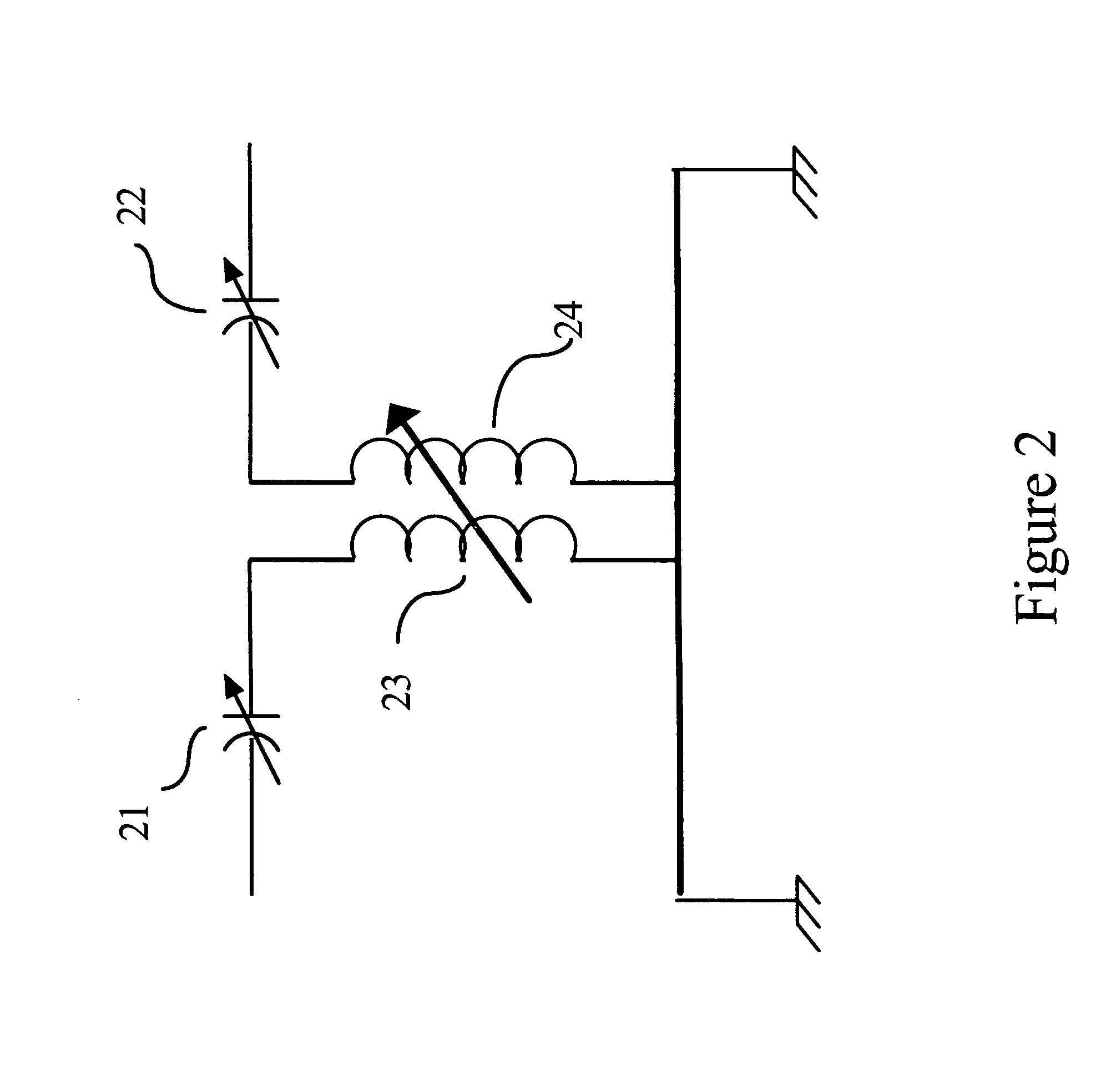
[0015] The present invention utilizes two tuned, mutually coupled coils, between which the coupling factor k can be varied. FIG. 2 shows the circuit diagram of this arrangement. The inductances of the primary 23 and the secondary 24 windings of the mutually coupled coils are equal and are tuned for series resonance at the operating carrier frequency by equal capacitors 21 and 22.

[0016] Capacitors 21 and 22 are tuned to resonate with the equal fixed inductance values of the primary 23 and the secondary 24 windings of the mutually coupled coils hence their reactances are numerically equal to XL(i.e. ωL=1 / ωC).

[0017]FIG. 3 shows the equivalent circuit of this arrangement shown in FIG. 2. An analysis of the equivalent circuit as shown in FIG. 3 proceeds as follows: [0018] Capacitors 25 and 28 have equal impedance values, of −jωL (since |XL|=|XC|); [0019] Inductors 26 and 27 have equal impedance values, jω(L−M); [0020] Inductor 29 has an impedance value of jωM; and [0021] Resistor 30 ha...


PUM


Abstract

An automatic matching and tuning unit (AMTU), which connects the output from a low or medium frequency, high power radio transmitter, which requires a 50 ohm terminating impedance, to an antenna with an input impedance comprising low resistance in series with a high capacitive reactance. Sensors measure the phase angle between the input current and voltage. The inductance of a series connected loading coil is continuously varied to resonate the antenna capacitance. The resulting input resistance is transformed to 50 ohms using a matching transformer and pair of resonant, mutually coupled coils with adjustable mutual coupling. Sensors measure the input resistance and continuously adjust the mutual coupling coefficient to maintain the required 50 ohm input impedance. Sensors measure the antenna current and vary the transmitter power level to keep it constant. A microcontroller processes all of the sensor outputs and provides serial communication with the transmitter.

Description

BACKGROUND OF THE INVENTION [0001] The present invention relates to a matching and tuning unit (AMTU), which connects the output from a low or medium frequency high power radio transmitter to an antenna with a complex input impedance. [0002] Most state-of-the-art high power radio transmitters which operate in the low or medium frequency bands unitize class D switching amplifiers which are much more efficient than their predecessors which operated as Class B amplifiers. This very significant improvement in efficiency has greatly reduced the size of the modem equipment, because large cooling surfaces are no longer required. As a result, these transmitters are much more susceptible than their predecessors to the effects of mismatch at their output terminals which results in reflected power being dissipated in the heat sinks of their final amplifiers. The task of establishing and maintaining an acceptable matched condition between transmitters and antennas, which operate in the low and ...

Claims


Application Information

Patent Timeline
IPC IPC(8): H01Q11/12H03H7/40H04B1/04
CPCH04B1/0458H03H7/40
Inventor PINKS, JOHN R.
Owner NAUTEL
Why Eureka
Try Eureka