Geometric replacements for defective bone

a technology of defective bone and osteosynthesis, applied in the field of repair of bone loss, can solve problems such as premature failure, and achieve the effect of reducing the need for revision and prolonging li

Inactive Publication Date: 2005-08-18
LENKBAR
View PDF17 Cites 39 Cited by
  • Summary
  • Abstract
  • Description
  • Claims
  • Application Information

AI Technical Summary

Benefits of technology

[0004] This invention is directed to the repair of bone voids and deficiencies, but instead of forming a planar, angled surface that could result in a “slip plane,” the invention utilizes an implant having a defined geometric pattern such as a stair-step, which mates with a corresponding stair-step pattern formed on the bone. Screws or alternative fasteners extend through one or mo

Problems solved by technology

The problem is that forces created in the hip may apply sh

Method used


Image

  • Geometric replacements for defective bone
  • Geometric replacements for defective bone
  • Geometric replacements for defective bone

Examples


Embodiment Construction

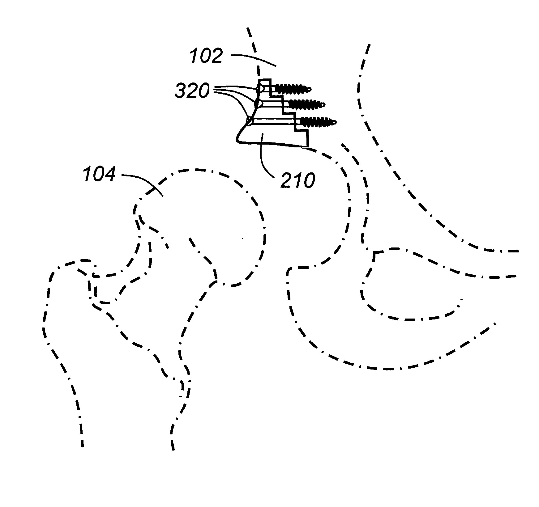
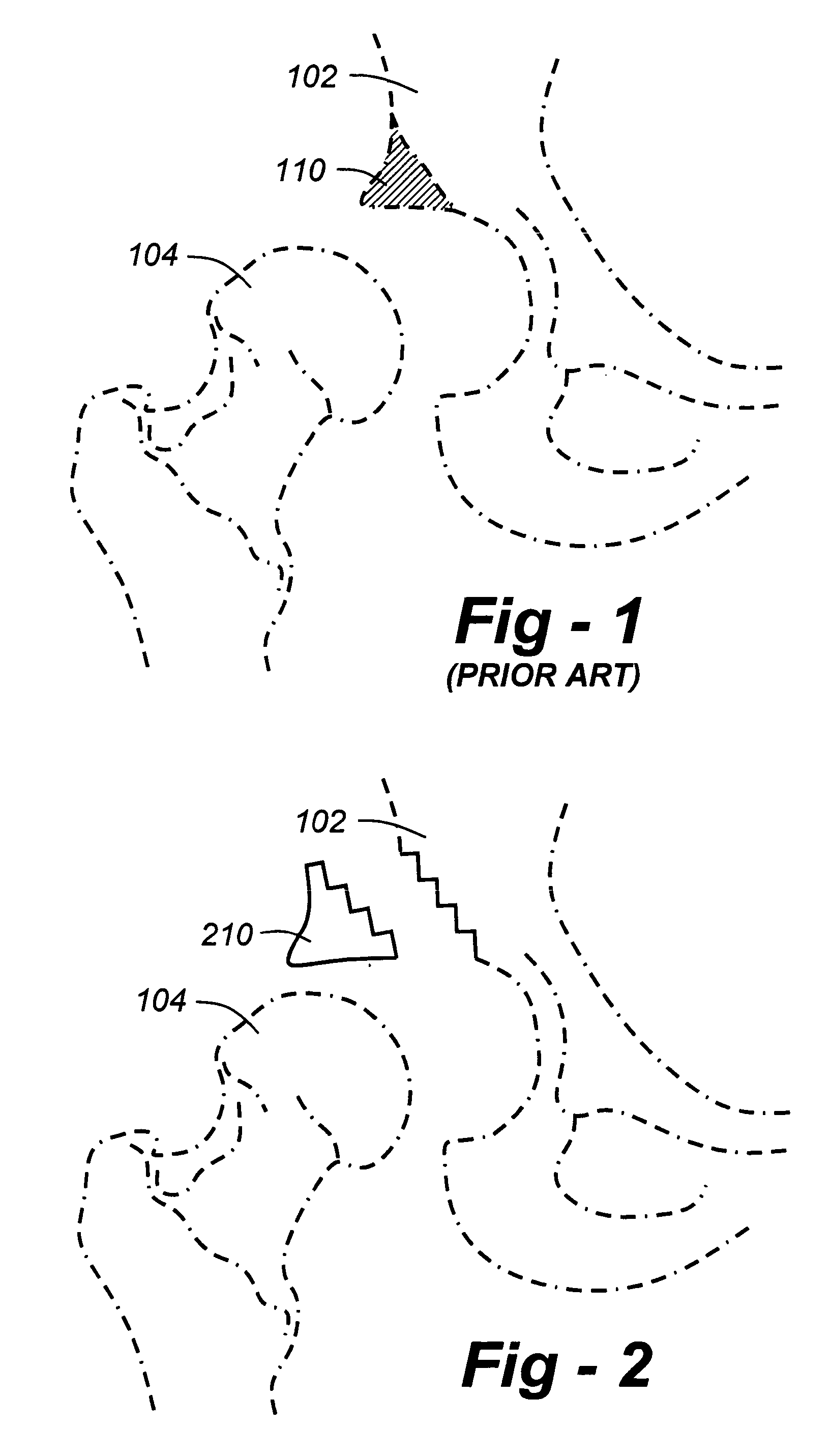
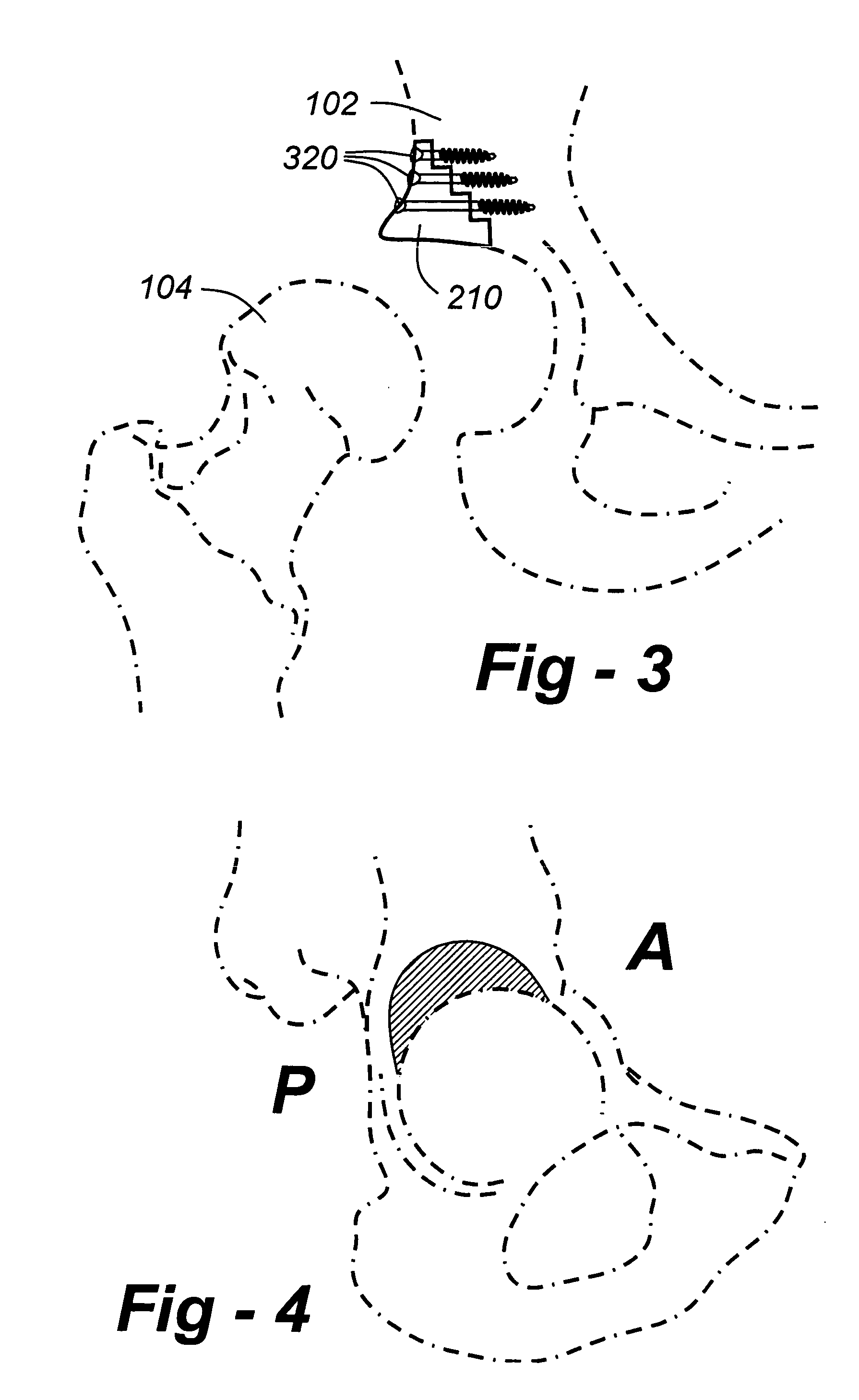
[0012]FIG. 2 is a drawing which shows a broad application of the invention. A bone such as pelvis 102 includes a defective region, but instead of forming a planar, angled surface that could result in a “slip plane,” the invention utilizes an implant 210 having a defined geometric pattern such as a stairstep, which mates with a corresponding stairstep pattern on the pelvis 102.

[0013]FIG. 3 shows how the component 210 would preferably be attached, namely, utilizing supplemental screws 320 which extend through one or more of the stairstep patterns, and into the bone, such that local interface around each fastener is substantially transverse to the axis of the fastener, thereby achieving a set of effective, compression bond. As such, shear stresses that might be associated with an angled, planar fixation are converted to compressive forces, leading to a longer life and a reduced need for revision.

[0014]FIG. 4 is a lateral view showing a defective region (hatched) oriented along anteri...


PUM


Abstract

In the repair of bone voids and deficiencies, rather than forming a planar, angled surface that could result in a “slip plane,” an implant features a defined geometric pattern such as a stair-step, which mates with a corresponding stair-step pattern formed on the bone. Screws or alternative fasteners extend through one or more of the stair-step patterns, and into the bone, such that local interface around each fastener is substantially transverse to the axis of the fastener, thereby achieving a set of effective, compression bond. As such, shear stresses that might be associated with an angled, planar fixation are converted to compressive forces, leading to a longer life and a reduced need for revision. Although in the preferred embodiment the plurality of surfaces defines a stair-step having right angles, other geometric patterns are applicable, so long as an irregular defect may be made more regular, and/or compressive forces are used to prevent shear stress. Cementation for may be used for fixation, and/or bone in-growth/on-growth. Although the invention is described in terms of the repair of a deficient acetabulum, the general idea is applicable to any region of the bone including, without limitation, glenoid repair, and tibial repair.

Description

REFERENCE TO RELATED APPLICATION [0001] This application claims priority from U.S. Provisional Patent Application Ser. No. 60 / 546,081, filed Feb. 18, 2004, the entire content of which is incorporated herein by reference.FIELD OF THE INVENTION [0002] This invention relates generally to the repair of bone loss and, in particular, to the use of an implant having a geometric bone-contacting surface operative to promote compression bonding and minimize premature failure caused by ‘slip planes.’BACKGROUND OF THE INVENTION [0003] With respect to the hip, FIG. 1 shows a prior-art situation, wherein a portion 110 of a socket associated with the pelvis 102 is deficient or otherwise defective, such that interaction with the head 104 of a proximal femur is inadequate and / or painful. Currently, although the portion 110 may be replaced, it is done on a generally hand-crafted basis. Typically, a planar, angled surface is formed in the acetabulum, and an implant having a corresponding planar surfac...

Claims


Application Information

Patent Timeline
IPC IPC(8): A61B17/16A61B17/17A61B17/80A61B17/86A61B19/00A61F2/00A61F2/28A61F2/30A61F2/34A61F2/46
CPCA61B17/1668A61F2230/0004A61B17/1684A61B17/1746A61B17/8061A61B17/8066A61B17/86A61B2017/1602A61B2019/304A61F2/28A61F2/30721A61F2002/30136A61F2002/30785A61F2002/30904A61F2002/3487A61F2002/4631A61B17/1675A61B2090/034
Inventor BERTRAM, MORTON III
Owner LENKBAR
Why Eureka
Try Eureka