Apparatus and method for forming a dual radius arch mounting structure

a technology of arched frame and accessory, applied in the field of arched frame accessory, can solve the problems of inability to manufacture preformed dual radius arched window frame supports, and inability to meet the needs of interior wall surfaces uniform and often times uneven, so as to prevent deformation or buckling, the effect of preventing deformation or buckling

Inactive Publication Date: 2005-08-25
BARRY MICHAEL A +1
View PDF50 Cites 14 Cited by
  • Summary
  • Abstract
  • Description
  • Claims
  • Application Information

AI Technical Summary

Benefits of technology

[0021] According to another aspect of the present invention a method for forming a dual radius arch window frame mounting structure utilizing a forming apparatus is provided. The method may include the steps of establishing a width W, arch height H, span length L and thickness T of a dual radius arch frame to be formed; defining the dual radius arch frame by selecting a left and right outer form radius R4 and positioning a left and right outer form having a radius R4 at a left and right pivot axis equally spaced a distance ½L−R4 from a centerpoint of a longitudinal member; further defining the dual radius arch frame by a radius defined by R3 and arc length measurement l and positioning a center arch span having a radius R3 and arc length measurement l in the forming apparatus such that the center arch span tangentially interconnects the left and right forms forming a complete dual radius arch form; applying a plurality of laminates with adhesive there between to the complete dual radius arch form to form a dual radius arch frame; surrounding the complete dual arch radius form and precut dual radius arch frame with a plurality of tensioned straps; allowing the adhesive to set-up; removing the plurality of tensioned straps from the forming apparatus; and cutting the dual radius arch frame along an arch baseline to provide a finished dual radius arch frame mounting structure.
[0022] The exemplary method of the present invention may also include utilizing at least one adjustable left strut assembly and right strut assembly to interconnect the left and right outer forms, respectively, to a vertical member laterally offset from the centerpoint of the longitudinal member and geometrically positioned underneath the center arch span, to provide additionally bracing to prevent the deformation or buckling of the complete dual arch radius form when the straps are applied to the dual radius arch frame. Moreover, the exemplary method may include utilizing a center strut assembly to interconnect left outer form and right outer form to prevent the deformation or buckling of the complete dual arch radius form when the straps are applied to the dual radius arch frame.

Problems solved by technology

Traditionally, the placement, mounting and peripheral enclosure of modern, interiorly mounted dual radius arched windows has heretofore required considerable skill and labor.
The above described prior art methods of mounting and finishing dual radius arched frames are known to be time consuming and to result in non-uniform and often times uneven interior wall surfaces.
However, Barry does not address how to manufacture preformed dual radius arch window frame supports.
And even if the method taught by Barry is applied to the manufacture of interior dual radius arch frame mounting structures, there are other existing challenges indigenous to the manufacture of dual radius arch preformed window frame supports which are not experienced in the manufacture of a more basic semi-circular arched preformed frame support.
Mainly, the problem is that dual radius arch designs may conform to numerous permutations and combinations of arch size selections, whereas, semi-circular arches only differ by radius.
A disadvantage to this process is that an individual jig must be built for each specific dual radius arch shape.
Building various jigs to meet various standard and custom ordered dual radius shapes becomes not only time consuming, but is also very expensive.

Method used


Image

  • Apparatus and method for forming a dual radius arch mounting structure
  • Apparatus and method for forming a dual radius arch mounting structure
  • Apparatus and method for forming a dual radius arch mounting structure

Examples


Embodiment Construction

[0036] The particulars shown herein are by way of example and for purposes of illustrative discussion of the embodiments of the present invention only and are presented in the cause of providing what is believed to be the most useful and readily understood description of the principles and conceptual aspects of the present invention. In this regard, no attempt is made to show structural details of the present invention in more detail than is necessary for the fundamental understanding of the present invention, the description taken with the drawings making apparent to those skilled in the art how the several forms of the present invention may be embodied in practice.

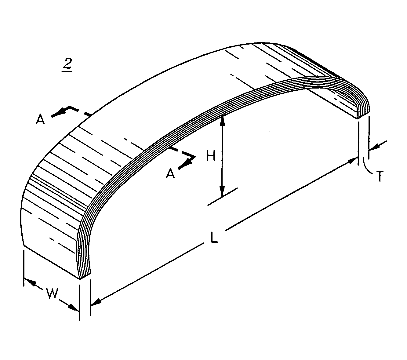
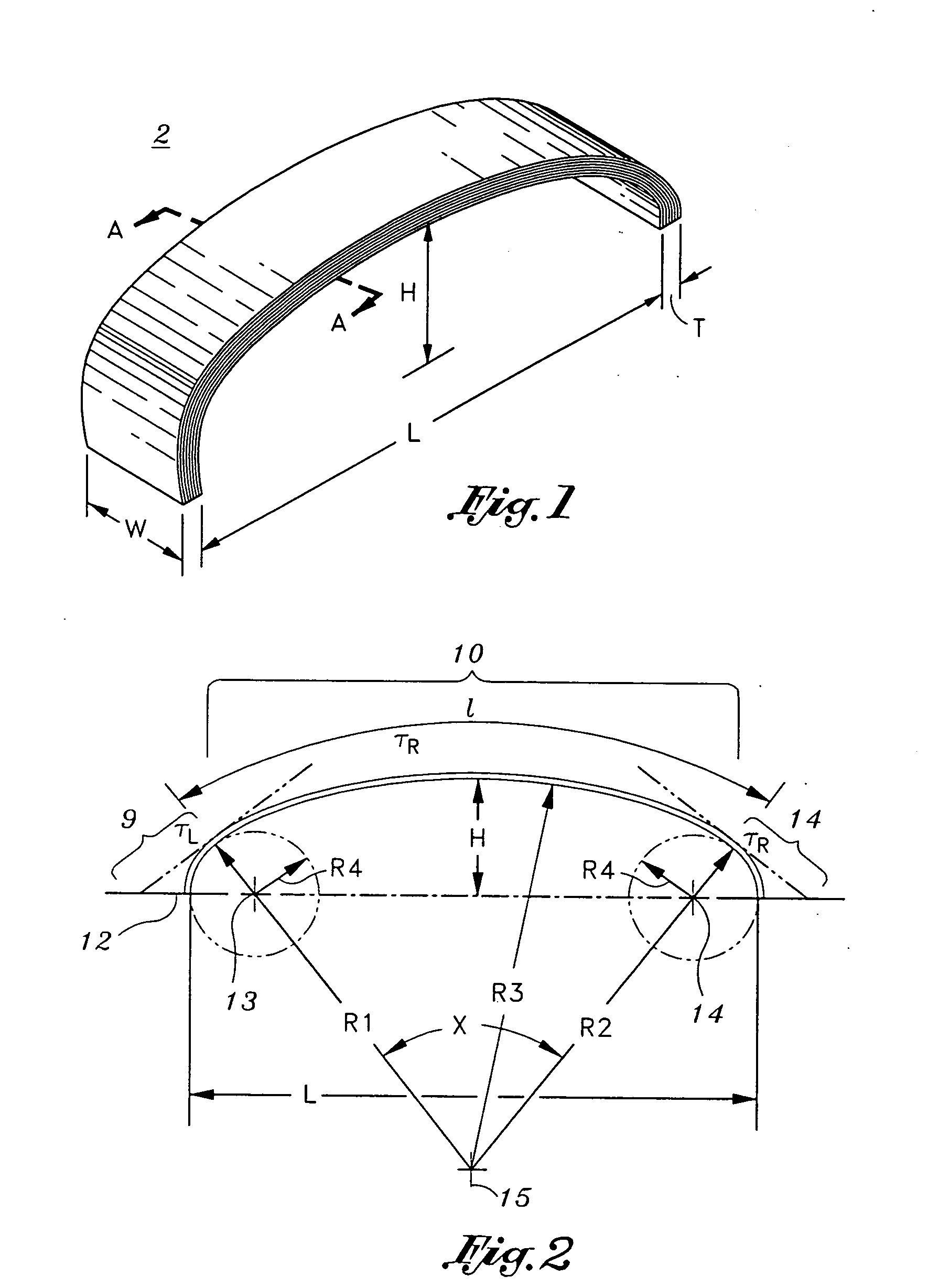
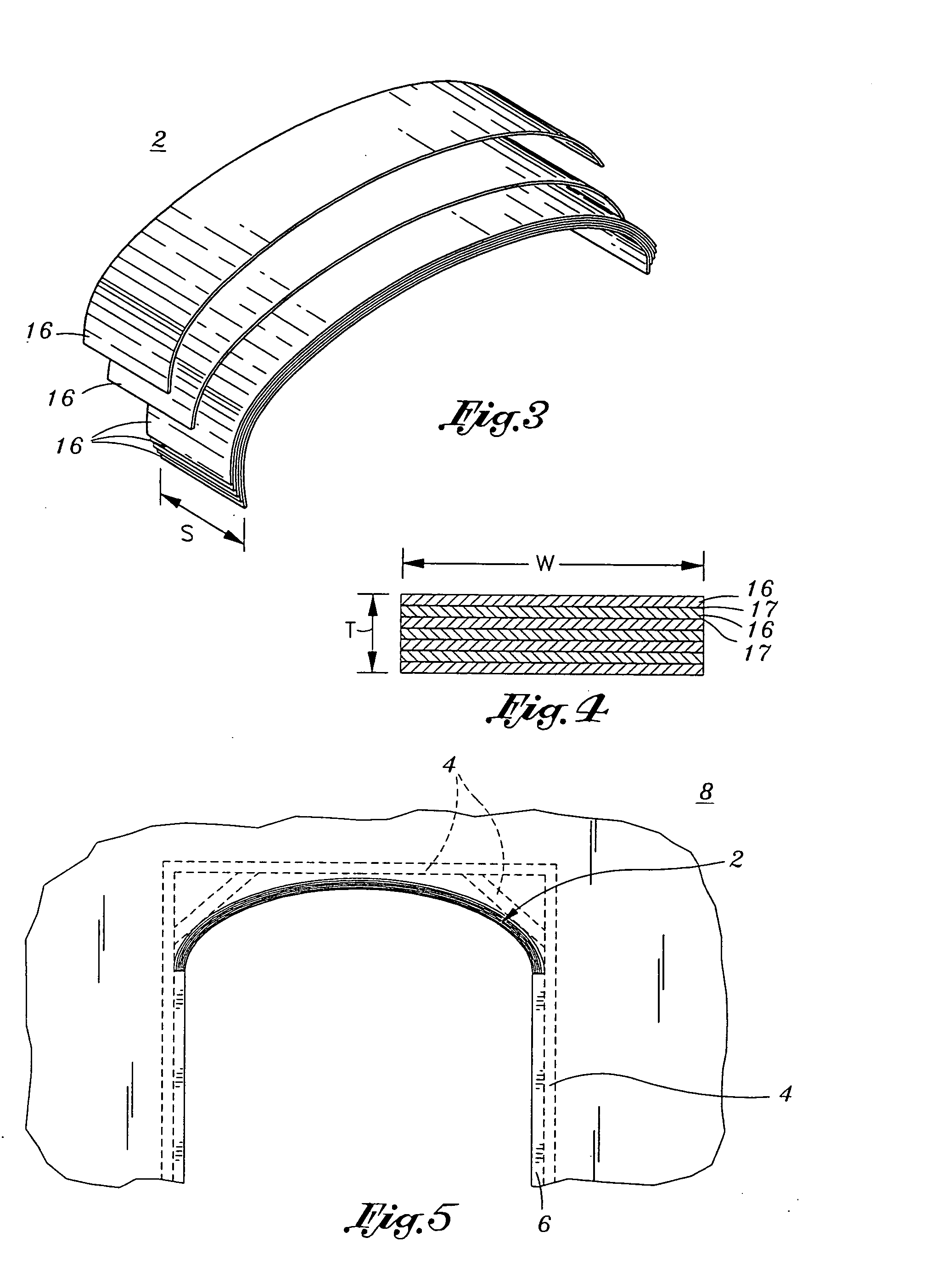
[0037] The present invention provides an apparatus or jig 5 and method for forming a dual radius arch mounting structure 2. A general description of the dual arch radius frame mounting structure 2 is initially provided. A detailed description of the forming apparatus or jig 5 is then provided. Finally, a method on how t...


PUM

PropertyMeasurementUnit
angleaaaaaaaaaa
distanceaaaaaaaaaa
sizeaaaaaaaaaa

Abstract

An apparatus and method is provided for forming a dual radius arch frame structure. The apparatus includes a longitudinal member having a centerline and centerpoint. A laterally adjustable support is further included which has one end attached to the centerpoint of the longitudinal member in a perpendicular orientation and a vertical support attached to a distal end of the laterally adjustable support. A left outer form is provided which has a generally semi-circular shaped arch centered and oriented about a left pivot axis located on the centerline a predetermined distance from the centerpoint. A right outer form is also provided which has a generally semi-circular shaped arch centered and oriented about a right pivot axis located on the centerline a predetermined distance from the centerpoint. Additionally, an arched shaped center cord is adapted to be connected to a receiving edge of the left outer form and of the right outer form in a tangentially continuous manner. Also, at least one adjustable left strut assembly interconnects the left outer form to the vertical support and at least one adjustable right strut assembly interconnects the right outer form to the vertical support.

Description

CROSS-REFERENCE TO RELATED APPLICATIONS [0001] Not Applicable STATEMENT RE: FEDERALLY SPONSORED RESEARCH / DEVELOPMENT [0002] Not Applicable BACKGROUND OF THE INVENTION [0003] 1. Field of the Invention [0004] The present invention relates to the art of building construction, and in particular, apparatuses and methods for forming arched frames that may be utilized in new construction or in retrofitting or remodeling existing structures. The present invention is even more particularly applicable to apparatuses and methods for forming dual radius arched doorway structures, niches and various interior openings. [0005] 2. Background of the Invention [0006] A dual radius arch frame is defined by a generally horizontal oriented base frame portion and a dual radius arch frame portion. Referring to FIG. 2, in general, the dual arch radius frame portion has three sections including a center arch span 10, a left downwardly curved section 9, and a right downwardly curved section 11. The center ar...

Claims


Application Information

Patent Timeline
Patent Type & Authority Applications(United States)
IPC IPC(8): B27D1/08B27H1/00B32B1/00E04B1/32
CPCB27D1/083B32B1/00B27H1/00B32B2419/00B32B21/02B32B21/042B32B21/13
Inventor BARRY, MICHAEL A.GOODWIN, GEORGE E.
Owner BARRY MICHAEL A
Why Eureka
Try Eureka