Home cooling cycle

Inactive Publication Date: 2005-08-25
AUBIN DOUGLAS EDWARD
View PDF4 Cites 6 Cited by
  • Summary
  • Abstract
  • Description
  • Claims
  • Application Information

AI Technical Summary

Benefits of technology

[0013] It is also ideally suited to wintertime savings. With the home facing north-south and with adequate south glass, solar heat gain coupled with a wood burning fireplace and the concrete mass, can smooth interior temperatures and reduce he

Problems solved by technology

However, this is not new technology; it is referenced in many books

Method used


Image

  • Home cooling cycle
  • Home cooling cycle
  • Home cooling cycle

Examples


Embodiment Construction

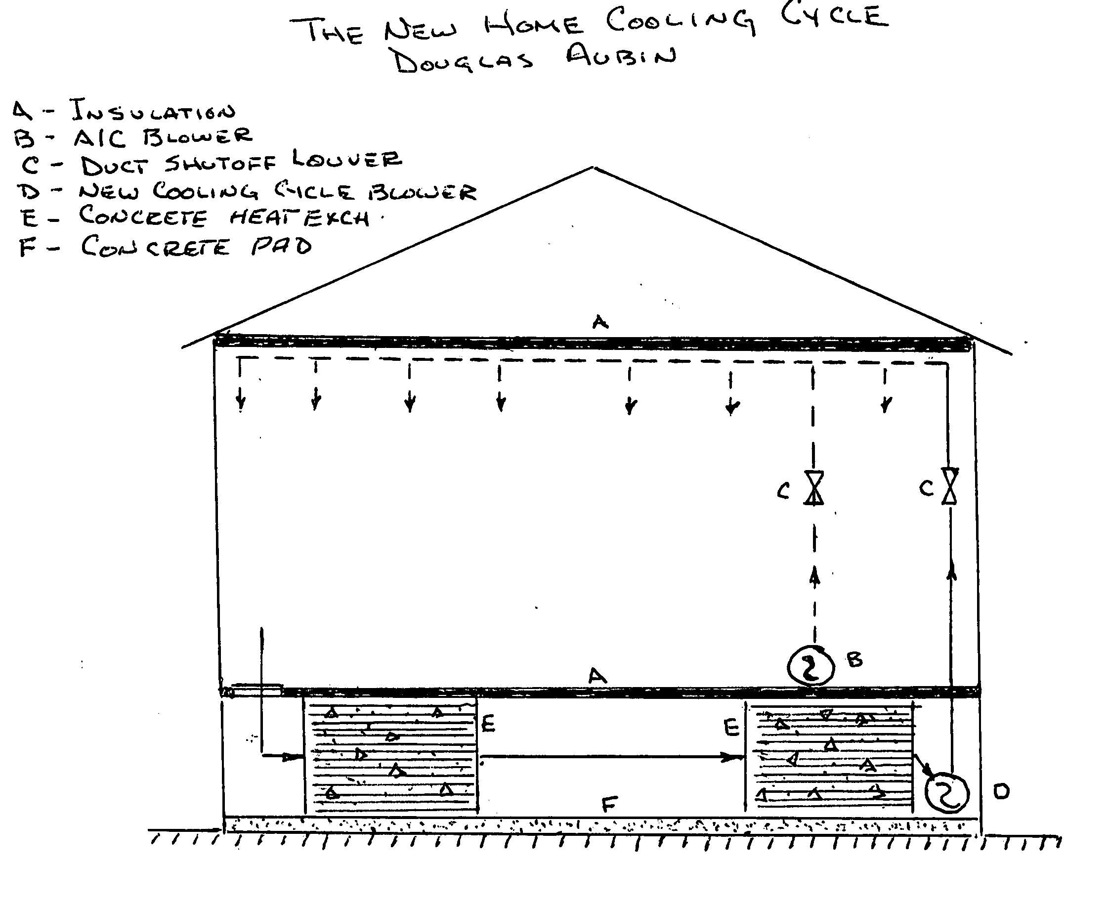
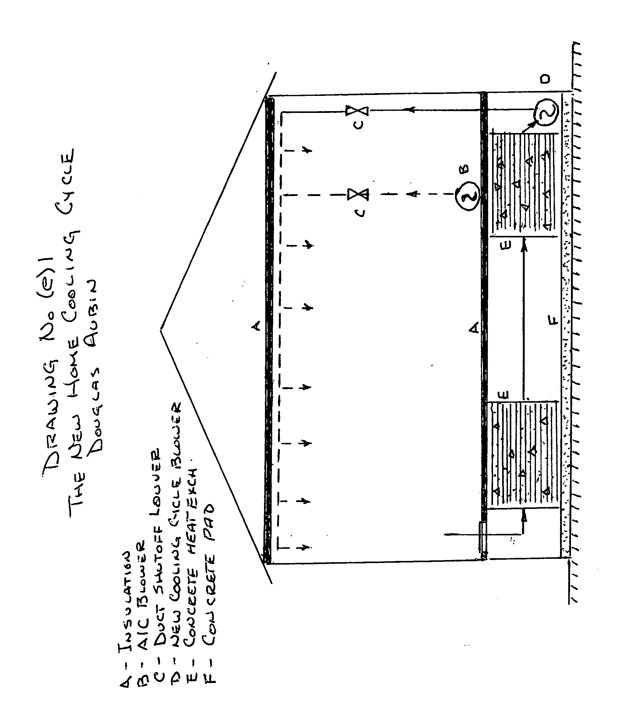
[0021] This invention proposes a home summer cooling cycle, in addition to the normal refrigerated air conditioning system. The cooling cycle utilizes a separate blower and a concrete mass located under the home between the floor and the ground. This blower and concrete mass are isolated from the home interior by the insulated flooring. The blower distributes air into the home interior using the normal air conditioning ductwork. It is important that this ductwork be located under the ceiling or under the flooring as in mobile homes and not in the attic.

[0022] Heat entering the home is absorbed into the air and interior walls and fixtures. Heated interior air is next routed via a filter-grill into the concrete mass area beneath the home. The concrete absorbs heat from the air, the air flows to the blower suction and returns to the home interior. See drawing (e)1. Calculations shown at the end of this section show that house daily interior air temperature should only rise 5° F. above...


PUM


Abstract

The heart of the “New Home Cooling Cycle” is a concrete heat exchanger located under the home. The heat exchanger is constructed of concrete and PVC piping. There are two flow passes. Each is ninety degrees from the other. On a hot sunny day, heat absorbed by air inside the home is routed through one pass of the heat exchanger where the heat is removed by absorption into the concrete, thus removing heat from the home. Air is circulated using a small electric blower. Air leaving the heat exchanger is cool and is returned to the home ready to absorb heat again. The recycled air absorbs additional heat and the cycle is repeated through the heat exchanger. Regeneration of the heat exchanger is accomplished at night. Cool night air is blown, using a small electric blower, through the heat exchanger second pass, ninety degrees to the absorbing pass. This cooling air absorbs heat from the heat exchanger and exhausts it back to the night air. The two heat exchanger passes are totally isolated to prevent moisture from entering the house circuit. This same cycle is used during winter. On a sunny winter day, solar heat and heat from a wood burning fireplace is absorbed by air inside the home and is routed through the heat exchanger as in the summer cooling cycle. Heat is removed and stored in the heat exchanger and cooled air is returned to the home where the cycle repeats. At night, heat stored in the heat exchanger is routed into the home. During winter, there is no regeneration required for the heat exchanger. Usage of refrigerated air conditioning is radically reduced. In some United States climates, it may be possible to eliminate refrigerated air conditioning.

Description

CROSS REFERENCE TO RELATED APPLICATIONS [0001] I have no knowledge of any related applications. STATEMENT OF FEDERALLY SPONSORED RESEARCH / DEVELOPMENT [0002] The invention submitted in this application is not federally sponsored. REFERENCE TO A “SEQUENCE LISTING”[0003] None BACKGROUND OF THE INVENTION [0004] Several years ago, my youngest son and I built a Passive Solar Energy home in San Marcos, Texas. The wintertime benefits of this type of design are well documented in numerous books and journals. We were also interested in the home's behavior during summertime. Of particular interest was the floor mass which was Saltillo tile on top of a concrete slab. During a June 100° F. day, with the home closed up and no air conditioning operating, we recorded hourly readings of interior air temperature, from 6 AM to 8 PM. Four thermometers were used. THE AIR TEMPERATURE INCREASED 10° F., from 70° F. to 80° F. We were amazed. However, this is not new technology; it is referenced in many book...

Claims


Application Information

Patent Timeline
IPC IPC(8): F24F5/00
CPCF24F5/0017Y02E70/30Y02E60/147Y02E60/14
Inventor AUBIN, DOUGLAS EDWARD
Owner AUBIN DOUGLAS EDWARD
Why Eureka
Try Eureka