
Enhanced performance reactive composite projectiles

a composite projectile and composite technology, applied in the field of reactive materials, can solve the problems of relatively low mechanical strength of reactive composite materials, aerodynamic instability, large amount of reaction energy, etc., and achieve the effect of enhancing projectile performance and enhancing projectile performan

Inactive Publication Date: 2005-08-25
THE UNITED STATES OF AMERICA AS REPRESENTED BY THE SECRETARY OF THE NAVY
View PDF23 Cites 26 Cited by
  • Summary
  • Abstract
  • Description
  • Claims
  • Application Information

AI Technical Summary

Benefits of technology

[0006] Accordingly, it is an object of the present invention to enhance the performance of a reactive composite projectile in terms of launch and in-flight integrity and / or target penetration and subsequent energy release.
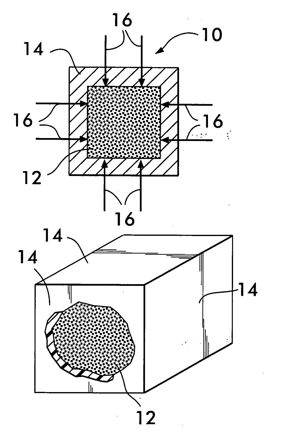
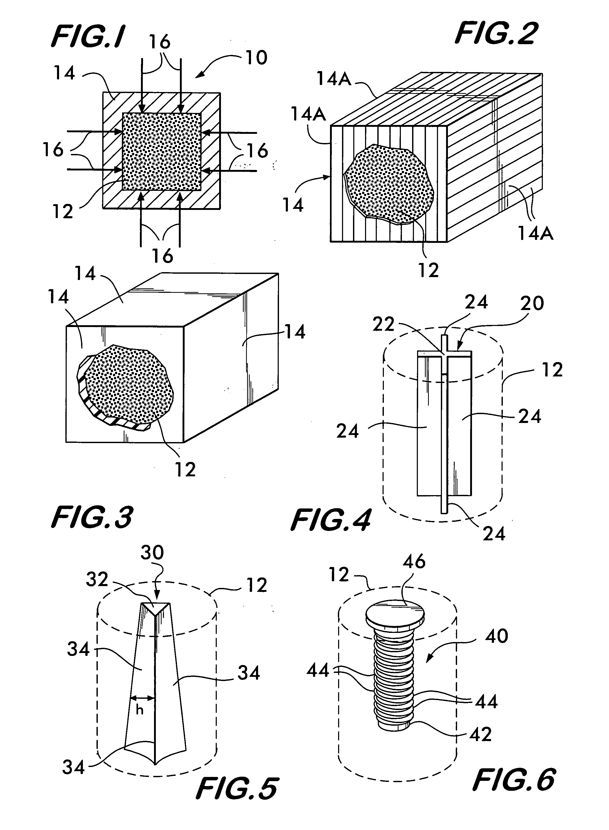
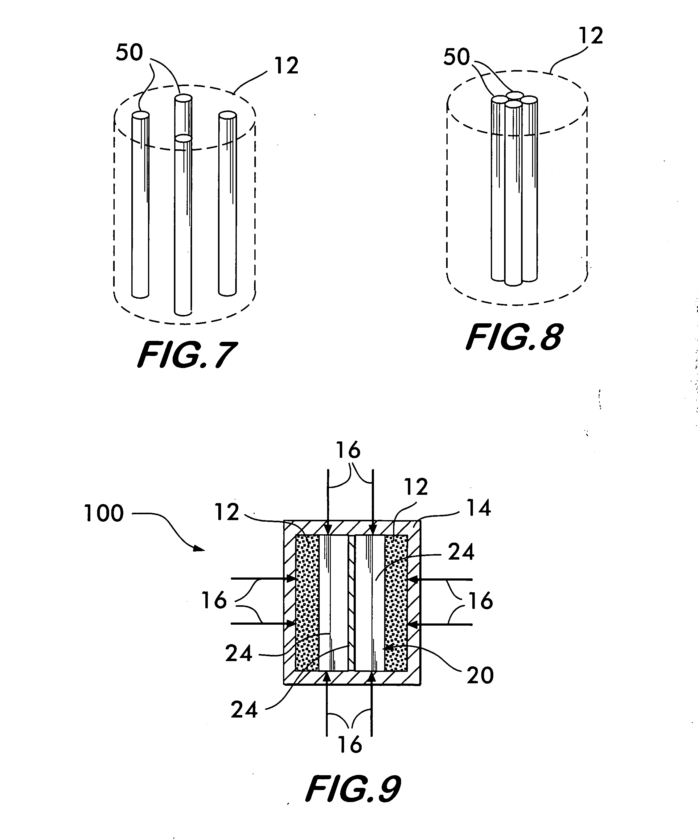
[0008] In accordance with the present invention, a reactive composite projectile includes a reactive composite material in a solid shape and an encasement material applied to and surrounding the solid shape for exerting compressive forces thereon. Additionally or alternatively, an elongate structure can be positioned in the solid shape. The elongate structure is made from a material having a mass density that is approximately 2 to 10 times the mass density of the reactive composite material. In general, the encasement material enhances projectile performance in terms of launch / in-flight integrity and while the elongate structure enhances projectile performance in terms of penetration / energy release.

Problems solved by technology

This reaction releases a large amount of energy.
The problems associated with reactive composite projectiles are two-fold.
However, reactive composite materials have relatively low mechanical strength.
This limits launch and in-flight speeds for such projectiles lest they break up at launch or during flight making them aerodynamically unstable and reducing their effectiveness at target impact.
Second, the relatively low strength and mass density of reactive composite projectiles limits their target penetration effectiveness on targets having thicker “skins”.

Method used


Image

  • Enhanced performance reactive composite projectiles
  • Enhanced performance reactive composite projectiles
  • Enhanced performance reactive composite projectiles

Examples


Embodiment Construction

[0018] Prior to describing the present invention, two terms used in the following description will first be defined. The first of these terms is “reactive composite material” and the second of these terms is “projectile”. As used herein, the term “reactive composite material” refers to any composite material having constituent components that will react together to release energy when subjected to a high force of impact. As is known in the art, typical reactive composite materials include one or more metals, one or more oxidizers and binder material. The choice of reactive composite material is not a limitation of the present invention. A typical example is aluminum polytetrafluoroethylene (Al-PTFE).

[0019] The term “projectile” as used herein refers to any body that is projected or impelled forward through a medium (e.g., air). The shape of the body is not a limitation of the present invention although regular body shapes (e.g., cylinders, spheres, cubes) will typically be used. Th...


PUM

PropertyMeasurementUnit
compressive forceaaaaaaaaaa
tensile forceaaaaaaaaaa
flexibleaaaaaaaaaa

Abstract

A reactive composite projectile includes a reactive composite material in a solid shape and an encasement material applied to and surrounding the solid shape for exerting compressive forces thereon. Additionally or alternatively, an elongate structure can be positioned in the solid shape. The elongate structure is made from a material having a mass density that is approximately 2 to 10 times the mass density of the reactive composite material.

Description

ORIGIN OF THE INVENTION [0001] The invention described herein was made in the performance of official duties by an employee of the Department of the Navy and may be manufactured, used, licensed by or for the Government for any governmental purpose without payment of any royalties thereon.FIELD OF THE INVENTION [0002] The invention relates generally to reactive materials, and more particularly to reactive material projectiles encased to enhance launch / in-flight integrity and aerodynamics, and / or having an insert that enhances performance in terms of target penetration and energy release. BACKGROUND OF THE INVENTION [0003] Reactive composite materials show promise for use as weapon projectiles designed to defeat a “protected” target. Such protected targets can be targets protected by a building structure or armor. Upon striking such a protected target, the energy of the impact serves as a catalyst that initiates a chemical reaction of the reactive composite material. This reaction rel...

Claims


Application Information

Patent Timeline
Patent Type & Authority Applications(United States)
IPC IPC(8): F42B12/06F42B12/44F42B12/46F42B12/78
CPCF42B12/06F42B12/78F42B12/46F42B12/44
Inventor NECHITAILO, NICHOLAS V.
Owner THE UNITED STATES OF AMERICA AS REPRESENTED BY THE SECRETARY OF THE NAVY
Learn More