Emission gas recycling equipment having butterfly valve
a technology of emission gas recycling and butterfly valve, which is applied in the direction of valve operating means/release devices, mechanical equipment, machines/engines, etc., can solve the problems of engine power reduction, engine driving performance reduction, and butterfly valve not being operated smoothly by an actuator such as the torque motor
- Summary
- Abstract
- Description
- Claims
- Application Information
AI Technical Summary
Benefits of technology
Problems solved by technology
Method used
Image
Examples
first embodiment
[0024] (First Embodiment)
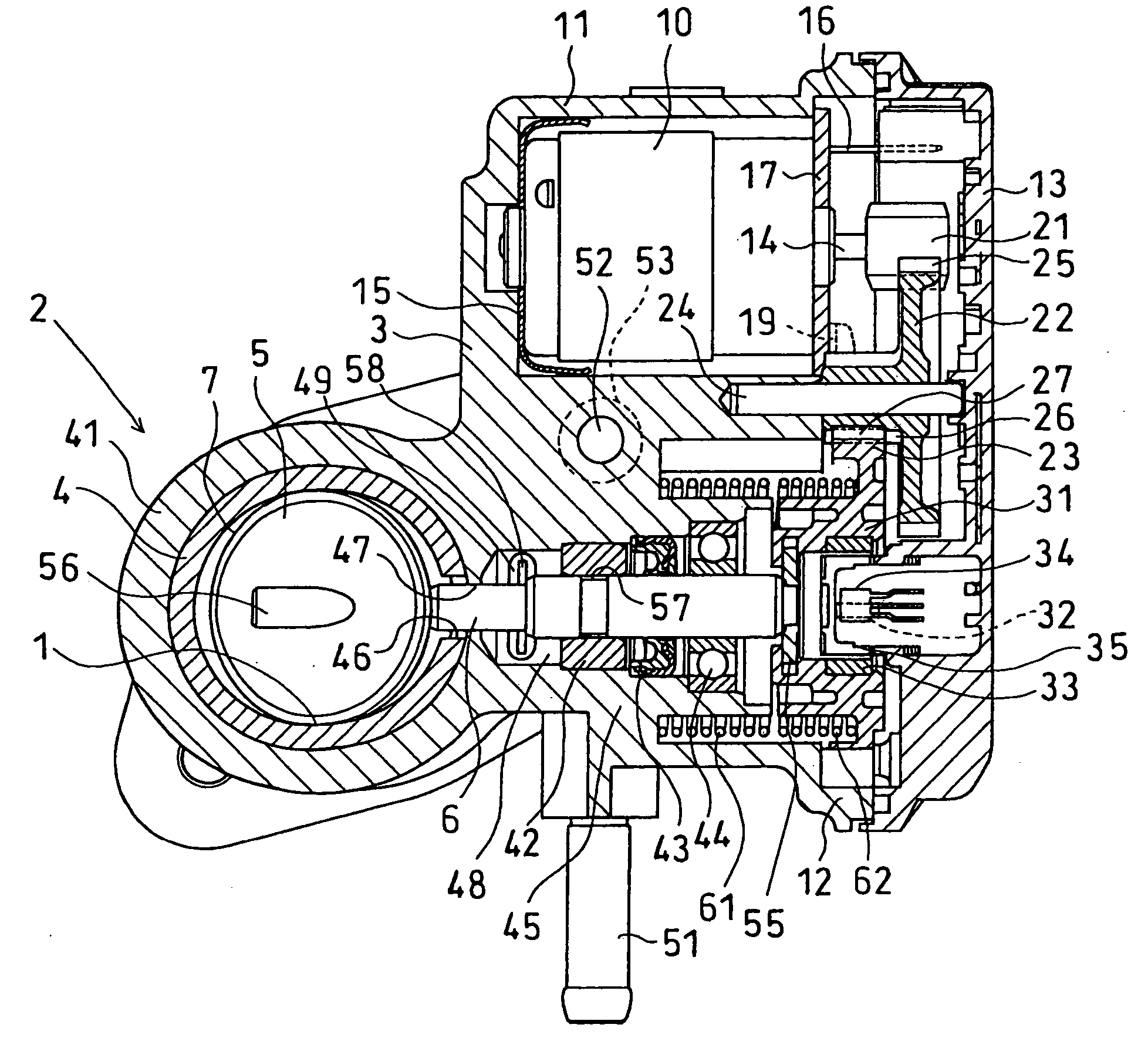
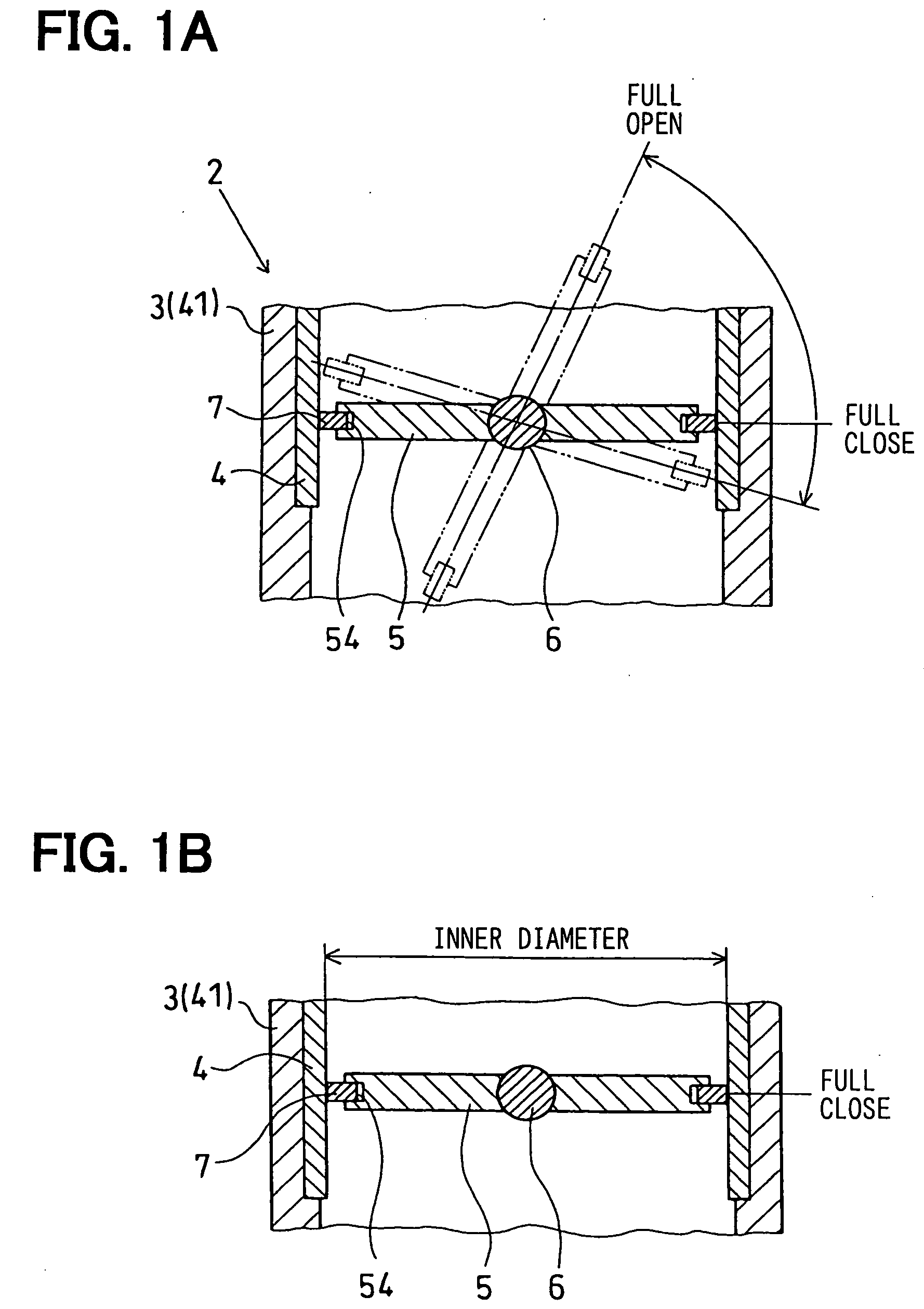
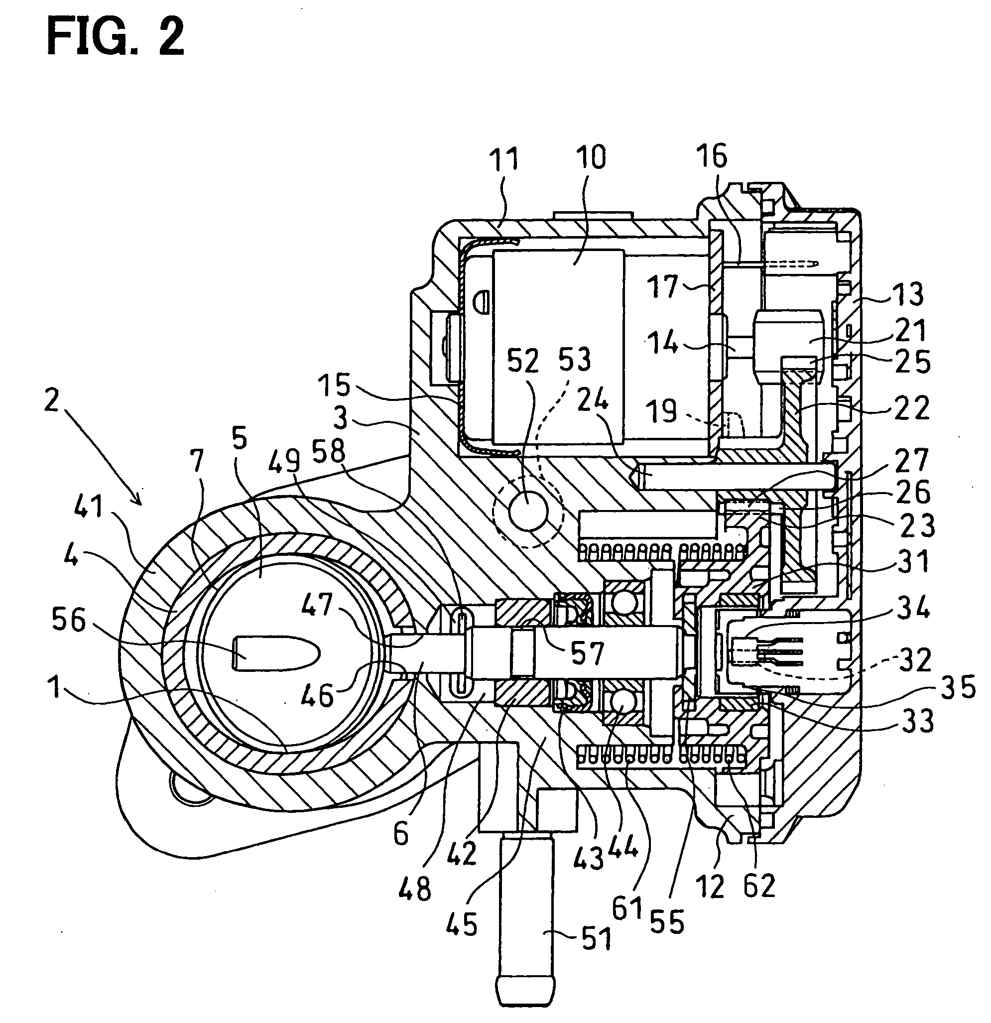
[0025] The inventors have preliminarily studies about emission gas recycling equipment having a butterfly valve, which is shown in FIGS. 6A and 6B. A recycling emission gas amount control valve is designed to include a nozzle 102, a valve shaft 103, a butterfly valve 104, and a seal ring 106. The nozzle 102 having a substantially ring shape is engaged to a valve housing 101. The valve shaft 103 is operated by a torque motor. The butterfly valve 104 rotates around a rotation center axis as a center of the valve shaft 103 in the nozzle 102. The seal ring 106 having a substantially ring shape is accommodated in a circumferential groove 105 of the butterfly valve 104. When the butterfly valve 104 is positioned at a valve full close position, the seal ring 106 can seal a ring shaped clearance by using an elastic deformation force in a radial direction of the seal ring 106. The ring shaped clearance is formed between the inner diameter surface of the nozzle 102 an...
second embodiment
[0064] (Second Embodiment)
[0065]FIGS. 4A ands 4B show a main part of an emission gas recycling amount control valve in emission gas recycling equipment according to a second embodiment of the present invention.
[0066] The emission gas recycling equipment according to this embodiment includes a return spring (not shown) as valve position holding means for stopping the butterfly valve 5 at the valve stop position passed over the valve full close position when the engine stops. In this case, the valve stop position is a position, at which the butterfly valve 5 is rotated by a predetermined rotation angle from the valve full close position in the valve closing direction. The return spring applies a force to the butterfly valve 5 in the returning direction from the valve full open position to the valve stop position across the valve full close position.
[0067] The equipment includes two protrusions (i.e., protruding portions, that are guides such as a rib) 71, 72 as the ring outer diamet...
third embodiment
[0070] (Third Embodiment)
[0071]FIGS. 5A and 5B show a main part of an emission gas recycling amount control valve in emission gas recycling equipment according to a third embodiment of the present invention.
[0072] Emission gas recycling equipment according to this embodiment includes a return spring (not shown) as valve position holding means for stopping the butterfly valve 5 at the valve stop position passed over the valve full close position when the engine stops, similar to the second embodiment. In this case, the valve stop position is a position, at which the butterfly valve 5 is rotated by a predetermined rotation angle from the valve full close position in the valve closing direction. The return spring applies a force to the butterfly valve 5 in the returning direction from the valve full open position to the valve stop position across the valve full close position.
[0073] Further, the equipment includes a seal ring construction as the ring outer diameter holding means. The...
PUM
 Abstract
Description
Claims
Application Information
 - R&D
- Intellectual Property
- Life Sciences
- Materials
- Tech Scout
- Unparalleled Data Quality
- Higher Quality Content
- 60% Fewer Hallucinations
Browse by: Latest US Patents, China's latest patents, Technical Efficacy Thesaurus, Application Domain, Technology Topic, Popular Technical Reports.
© 2025 PatSnap. All rights reserved.Legal|Privacy policy|Modern Slavery Act Transparency Statement|Sitemap|About US| Contact US: help@patsnap.com


