PLL circuit

a technology of pll circuit and circuit board, applied in pulse generators, pulse techniques, instruments, etc., can solve the problems of reduced cost, inability to handle a case, and according to pll circuit, and achieve excellent properties, excellent properties, and high precision.

Inactive Publication Date: 2005-08-25
PANASONIC CORP
View PDF2 Cites 4 Cited by
  • Summary
  • Abstract
  • Description
  • Claims
  • Application Information

AI Technical Summary

Benefits of technology

[0030] In this configuration, dispersion in the properties between the first and second voltage controlled oscillators during manufacture can be corrected, and thus, a PLL operation having higher precision becomes possible.
[0031] The frequency of the second voltage controlled oscillator which has been stabilized by the PLL operation that utilizes a reference frequency signal is switched in the PLL circuit of the first invention, which, thereby, can handle two or more different frequencies of the first voltage controlled oscillator which are controlled by the same frequency control voltage. In this configuration, the frequency of the first voltage controlled oscillator can be stabilized, and thus, it is possible to gain a PLL circuit having excellent properties.
[0032] In addition, also in the case where the frequency of the reference frequency signal is switched in the second voltage controlled oscillator which has been stabilized by means of the PLL operation that utilizes the reference frequency signal, the PLL circuit handles two or more different reference frequencies of the first voltage controlled oscillator which are controlled by the same frequency control voltage. In this configuration, the frequency of the first voltage controlled oscillator can be stabilized, and thus, it is possible to gain a PLL circuit having excellent properties.
[0033] The frequency of the second voltage controlled oscillator which has been stabilized by the PLL operation that utilizes a reference frequency signal is switched in the PLL circuit of the second invention, which, thereby, can handle two or more different frequencies of the first voltage controlled oscillator which are utilized for a video detector and controlled by the same frequency control voltage. In this configuration, the frequency of the first voltage controlled oscillator can be stabilized, and thus, it is possible to gain a video detection circuit having excellent properties.
[0034] In addition, also in the case where the frequency of the reference frequency signal is switched in the second voltage controlled oscillator which has been stabilized by means of the PLL operation that utilizes the reference frequency signal, the PLL circuit handles two or more different reference frequencies of the first voltage controlled oscillator which are utilized for a video detector and controlled by the same frequency control voltage. In this configuration, the frequency of the first voltage controlled oscillator can be stabilized, and thus, it is possible to gain a video detection circuit having excellent properties.
[0035] Furthermore, the oscillatory frequency of the second voltage controlled oscillator can be adjusted, and thereby, it becomes possible to gain a PLL circuit having high frequency precision.

Problems solved by technology

However, the PLL circuit according to the prior art which is formed as shown in FIG. 4, cannot handle a case where there are a number of input frequencies and reference frequency signal sources.
Therefore, in order to apply this type of PLL circuit to a television receiver and the like, it is necessary to prepare PLL circuits having voltage controlled oscillators and reference frequency signal sources for different frequencies in accordance with the applied frequencies, which is extremely disadvantageous, taking reduction in costs into consideration.

Method used


Image

  • PLL circuit
  • PLL circuit
  • PLL circuit

Examples


embodiment 1

[0041] (Embodiment 1)

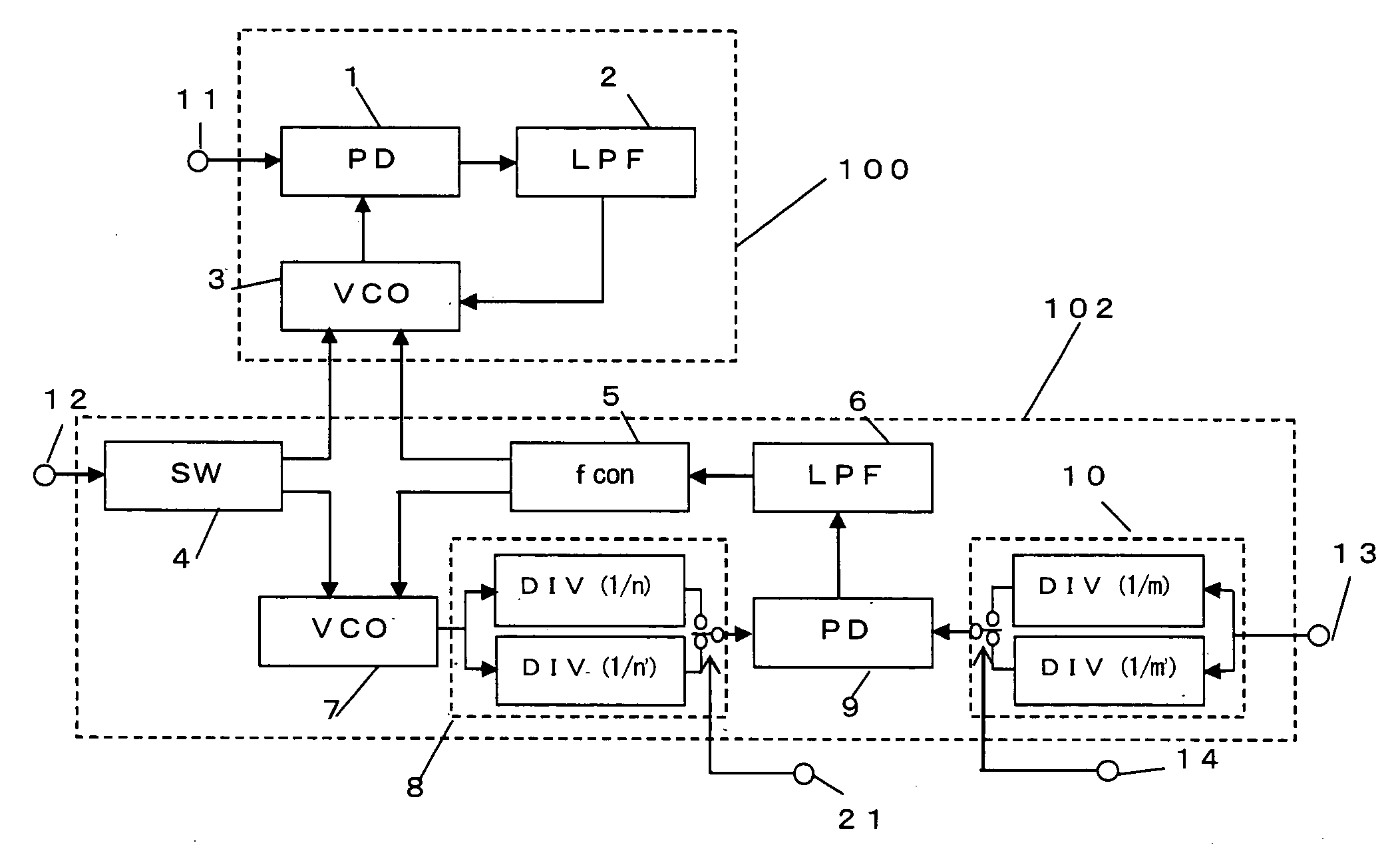
[0042] In the following, a PLL circuit according to Embodiment 1 of the present invention is described in reference to FIG. 1.

[0043]FIG. 1 is a block diagram showing the configuration of a PLL circuit according to Embodiment 1 of the present invention, and the same symbols are used for parts that are the same as in the prior art.

[0044] This PLL circuit is formed of first and second PLL circuit parts 100 and 102. First PLL circuit part 100 is formed of a first phase detector 1, a first low pass filter 2 and a first voltage controlled oscillator 3. Second PLL circuit part 102 is formed of a second voltage controlled oscillator 7, a second phase detector 9, a second low pass filter 6, a frequency control circuit 5 for supplying a frequency control voltage to first and second voltage controlled oscillators 3 and 7, a first variable frequency divider 10, a second variable frequency divider 8 and a frequency switching circuit 4.

[0045] Here, voltage controlled oscil...

embodiment 2

[0067] (Embodiment 2)

[0068] In the following, a PLL circuit according to Embodiment 2 of the present invention is described in reference to FIG. 2.

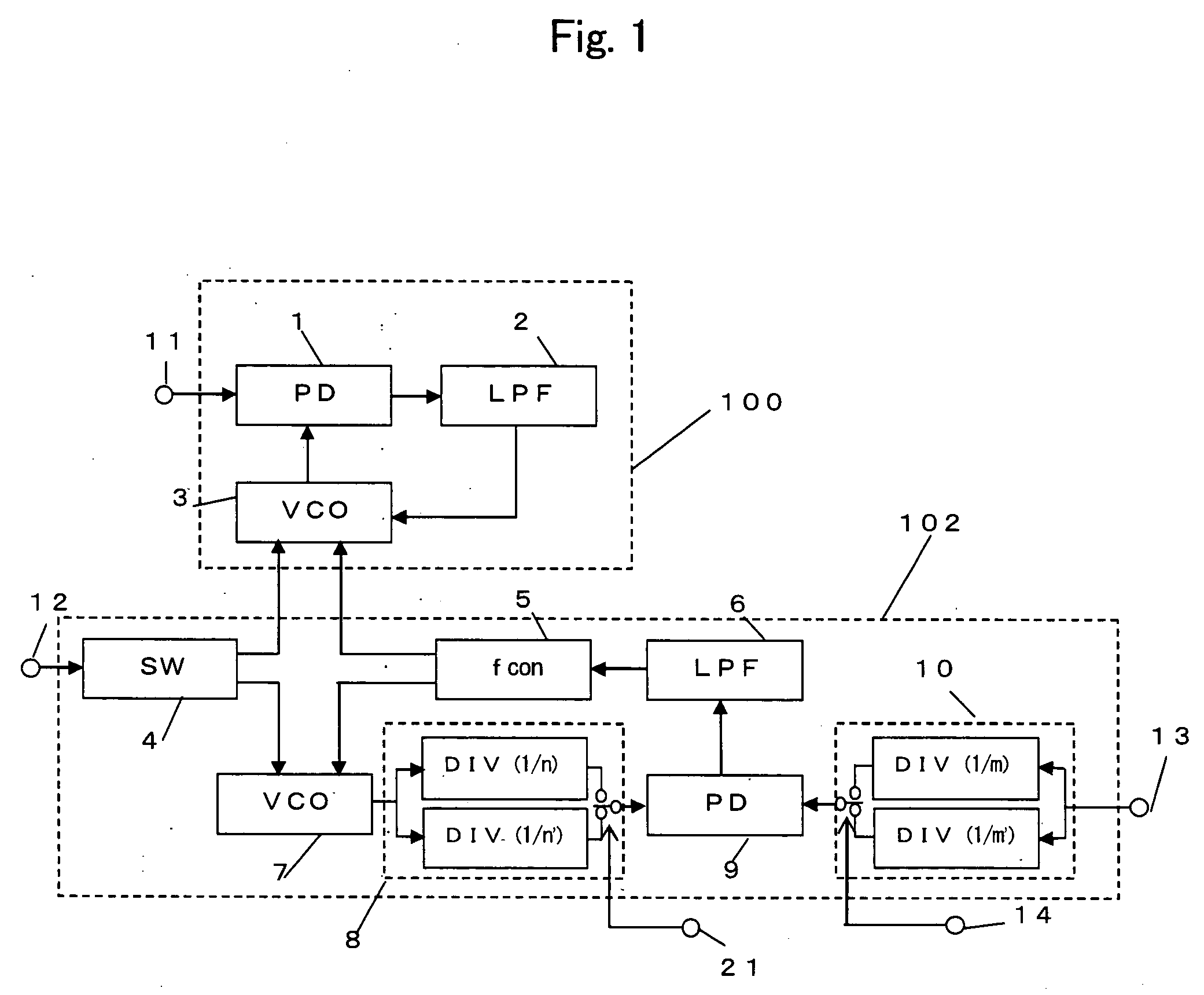
[0069]FIG. 2 is a block diagram showing the configuration of the PLL circuit according to Embodiment 2 of the present invention, and the same numbers are attached to parts that are the same as those of Embodiment 1.

[0070] This PLL circuit is formed of first and second PLL circuit parts 103 and 104. First PLL circuit part 103 is formed of a first phase detector 1, a first low pass filter 2, a first voltage controlled oscillator 3 and a phase shifter 15. Second PLL circuit part 104 is formed of a second voltage controlled oscillator 7, a second phase detector 9, a second low pass filter6, a frequency control circuit 5 for supplying a frequency control voltage to first and second voltage controlled oscillators 3 and 7, a first variable frequency divider 10, a second variable frequency divider 8 and a frequency switching circuit 4.

[0071] T...

embodiment 3

[0089] (Embodiment 3)

[0090] In the following, a PLL circuit according to Embodiment 3 of the present invention is described in reference to FIG. 3.

[0091]FIG. 3 is a block diagram showing the configuration of a PLL circuit according to Embodiment 3 of the present invention, and the same numbers are attached to parts that are the same as those of Embodiment 2.

[0092] This PLL circuit is formed of first and second PLL circuit parts 103 and 104, as well as a frequency adjusting circuit 105. First PLL circuit part 103 is formed of a first phase detector 1, a first low pass filter 2, a first voltage controlled oscillator 3 and a phase shifter 15. Second PLL circuit part 104 is formed of a second voltage controlled oscillator 7, a second phase detector 9, a second low pass filter 6, a frequency control circuit 5 for supplying frequency control voltages to first and second voltage controlled oscillators 3 and 7, a first variable frequency divider 10, a second variable frequency divider 8 a...


PUM


Abstract

The frequency of a first voltage controlled oscillator is stabilized in a first PLL circuit part into which a reference frequency signal is inputted. In addition, a second PLL circuit part is formed by inputting a control voltage which is the same as the frequency control voltage of the first voltage controlled oscillator into a second voltage controlled oscillator having the same configuration as the first voltage controlled oscillator. The first PLL circuit part is provided with first and second variable frequency dividers which respectively divide the reference frequency signal and the output of the first voltage controlled oscillator. In response to an input signal into the second PLL circuit part, the free-running frequencies of the second and first voltage controlled oscillators are switched, and at the same time, the division ratio of first and second variable frequency dividers are switched.

Description

Background of the Invention [0001] 1. Field of the Invention [0002] The present invention relates to a PLL circuit that utilizes a voltage controlled oscillator which is built into a semiconductor integrated circuit, and which has little dispersion in free-running frequency. [0003] 2. Prior Art [0004] In recent years, reduction in accessory parts and cost for adjustment has come into demand, as the price of television receivers and the like has lowered. In addition, oscillators which used to be difficult to completely build into an integrated circuit have been integrated, and the required performance thereof has also been increased. [0005] From among these, the degree of stability of free-running frequency in a voltage controlled oscillator that forms a PLL circuit greatly influences the performance of the formed PLL circuit, and in some cases, causes an unlocking phenomenon. Therefore, it is particularly important to stabilize free-running frequency. [0006] Furthermore, in some cas...

Claims


Application Information

Patent Timeline
Patent Type & Authority Applications(United States)
IPC IPC(8): H03L7/00H03L7/087H03L7/07
CPCH03L7/07H03L2207/06H03L7/0805
Inventor OBA, YASUOIKUMA, MAKOTO
Owner PANASONIC CORP
Why Eureka
Try Eureka