Electro-active spectacle employing modal liquid crystal lenses

a liquid crystal lens and electro-active technology, applied in the direction of immunoglobulins against animals/humans, peptides, immunoglobulins against cytokines/lymphocytosis/interferons, etc., can solve the problems of limiting the practical use of spectacle lenses, lenses are not completely transparent, and lenses have a relatively short response tim

Inactive Publication Date: 2005-08-25
E VISION LLC
View PDF51 Cites 100 Cited by
  • Summary
  • Abstract
  • Description
  • Claims
  • Application Information

AI Technical Summary

Problems solved by technology

While such modal liquid crystal lenses offer several advantages in terms of continuous optical power tuning and simplicity of design, they have several limitations that hinder their practical use as spectacle lenses, in particular, a lens for the treatment of presbyopia.
For example, such lenses are not completely transparent, and use visible metallic electrodes.
In addition, such lenses are not constructed in a manner that allows for them to be cut and shaped so that they may be placed within a frame.
Moreover, such lenses do not have a relatively quick response time (for example, less than 30 milliseconds) so that the optical power changes faster than the wearer's eye can detect, and do not account for a step change in optical power with an adjacent base lens used to provide a distance correction.
This leads to discomfort for the wearer, and also detracts from the cosmetic appearance of the lens.

Method used


Image

  • Electro-active spectacle employing modal liquid crystal lenses
  • Electro-active spectacle employing modal liquid crystal lenses
  • Electro-active spectacle employing modal liquid crystal lenses

Examples


Embodiment Construction

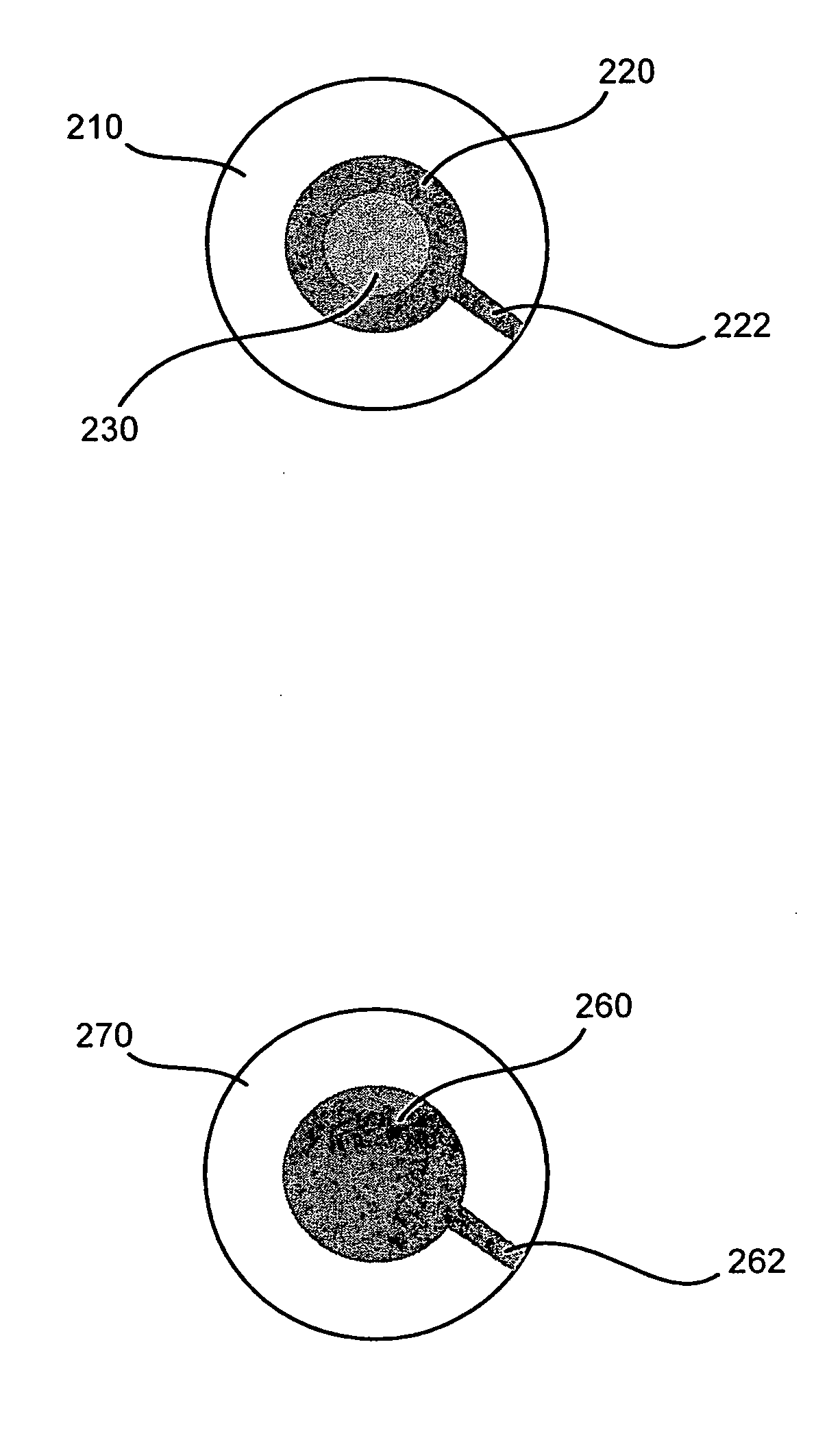
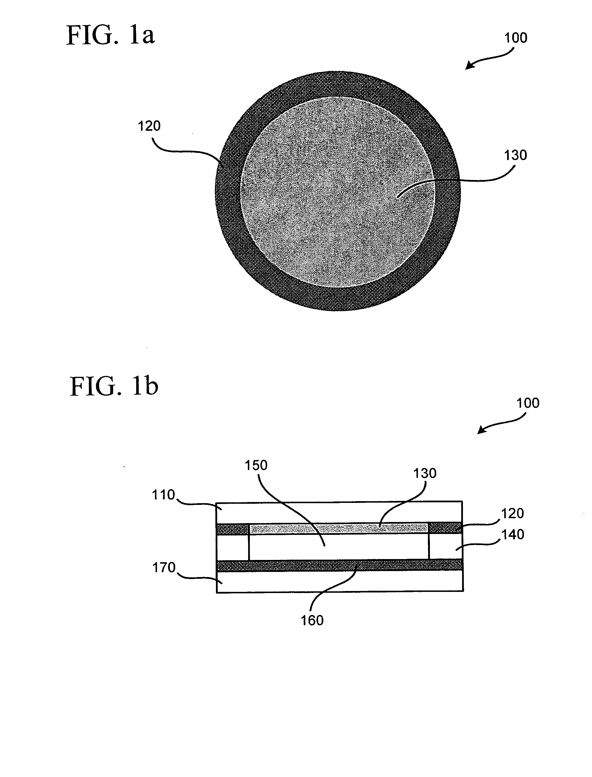
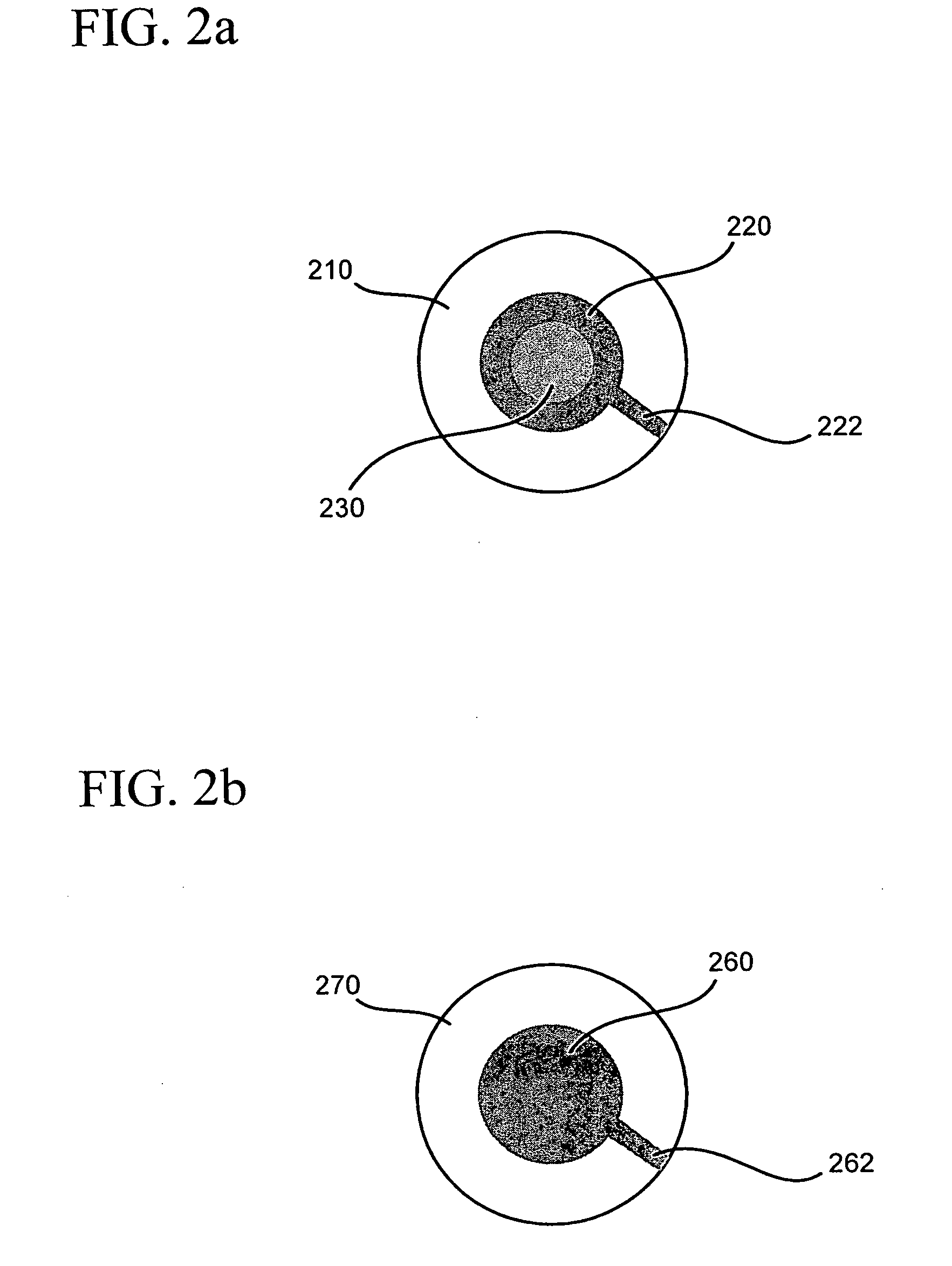
[0019] Various embodiments of electro-active spectacle lenses and spectacles employing modal liquid crystal lens assemblies, and methods of manufacturing such electro-active spectacles lenses are described herein. These lenses may be used to provide vision correction for one or more focal lengths, and may further correct non-conventional refractive error including higher order aberrations.

[0020] To assist with understanding certain embodiments described herein, explanations of various terms are provided. “Attaching” can include bonding, depositing, adhering, and other well-known attachment methods. A “controller” can include or be included in a processor, a microprocessor, an integrated circuit, a computer chip, and / or a chip. A “conductive bus” operates to conduct data in the form of an electrical signal from one place to another place. “Near distance refractive error” can include presbyopia and any other refractive error needed to be corrected for one to see clearly at near dista...


PUM

PropertyMeasurementUnit
thicknessaaaaaaaaaa
conductivityaaaaaaaaaa
voltageaaaaaaaaaa

Abstract

An electro-active spectacle lens is disclosed. The spectacle lens comprises a first substrate having a first outer region and first inner region, a first electrode layer disposed adjacent to the first inner region, the first electrode layer including an outer electrode region having a first conductivity and an inner electrode region having a second conductivity, the first conductivity being greater than the second conductivity, a second substrate having a second outer region and second inner region, a second electrode layer disposed adjacent to the second inner region, the second electrode layer having a third conductivity, and an electro-active cell disposed between the first electrode layer and the second electrode layer, the electro-active cell containing an electro-active material. The first outer region and second outer region are configurable for fitting the spectacle lens within a lens frame without altering the electro-active cell.

Description

[0001] The present application claims priority to U.S. Provisional Application No. 60 / 536,238 filed Jan. 14, 2004. This application is also a continuation-in-part of U.S. patent application Ser. No. 10 / 664,112 filed Aug. 20, 2003, which claims the benefit of U.S. Provisional Application No. 60 / 404,657 filed Aug. 20, 2002. U.S. patent application Ser. No. 10 / 664,112 is also a continuation-in-part of U.S. patent application Ser. No. 10 / 422,128 filed Apr. 24, 2003, which claims the benefit of U.S. Provisional Application No. 60 / 375,028, filed Apr. 25, 2002, and which is a continuation-in-part of U.S. patent application Ser. No. 10 / 387,143, filed Mar. 12, 2003, which claims the benefit of U.S. Provisional Application Nos. 60 / 363,549, filed Mar. 13, 2002 and 60 / 401,700, filed Aug. 7, 2002, and which is a continuation-in-part of U.S. patent application Ser. No. 10 / 281,204, filed Oct. 28, 2002 and Ser. No. 10 / 046,244, filed Jan. 16, 2002. U.S. patent application Ser. No. 10 / 281,204 is a co...

Claims


Application Information

Patent Timeline
Patent Type & Authority Applications(United States)
IPC IPC(8): A61K38/00C07K14/54C07K16/24C07K16/28G02B17/06G02B17/08G02B27/01G02C7/04G02C7/10G02F1/1333G02F1/1335G02F1/1341G02F1/1343G02F1/29
CPCA61K38/00G02F2001/13415C07K14/5443C07K16/244C07K16/2866C07K2319/00G02B27/017G02C7/04G02C7/048G02C7/083G02F1/133371G02F1/133553G02F1/1341G02F1/134309G02F1/29A61K2039/505G02F1/13415
Inventor BLUM, RONALD D.KOKONASKI, WILLIAMDUSTON, DWIGHT P.
Owner E VISION LLC
Why Eureka
Try Eureka