Laser vibrometry with coherent detection

Inactive Publication Date: 2005-08-25
CELIGHT
View PDF16 Cites 10 Cited by
  • Summary
  • Abstract
  • Description
  • Claims
  • Application Information

AI Technical Summary

Benefits of technology

[0015] In another embodiment of the present invention, a method is provided for determining information about a surface vibration at a remote location. An optical system is provided that produces at least first and second beams. The first and second beams are directed to an interrogated surface located remotely from the optical system. A third beam is formed and has a phase change relative to the first and second beams that corresponds with a surface vibration of the interrogated surface. A phase of the first and the second beams is changed by Doppler

Problems solved by technology

The disadvantage of the described above system is in rather low sensitivity of the signal detection, and further improvement o

Method used


Image

  • Laser vibrometry with coherent detection
  • Laser vibrometry with coherent detection
  • Laser vibrometry with coherent detection

Examples


Embodiment Construction

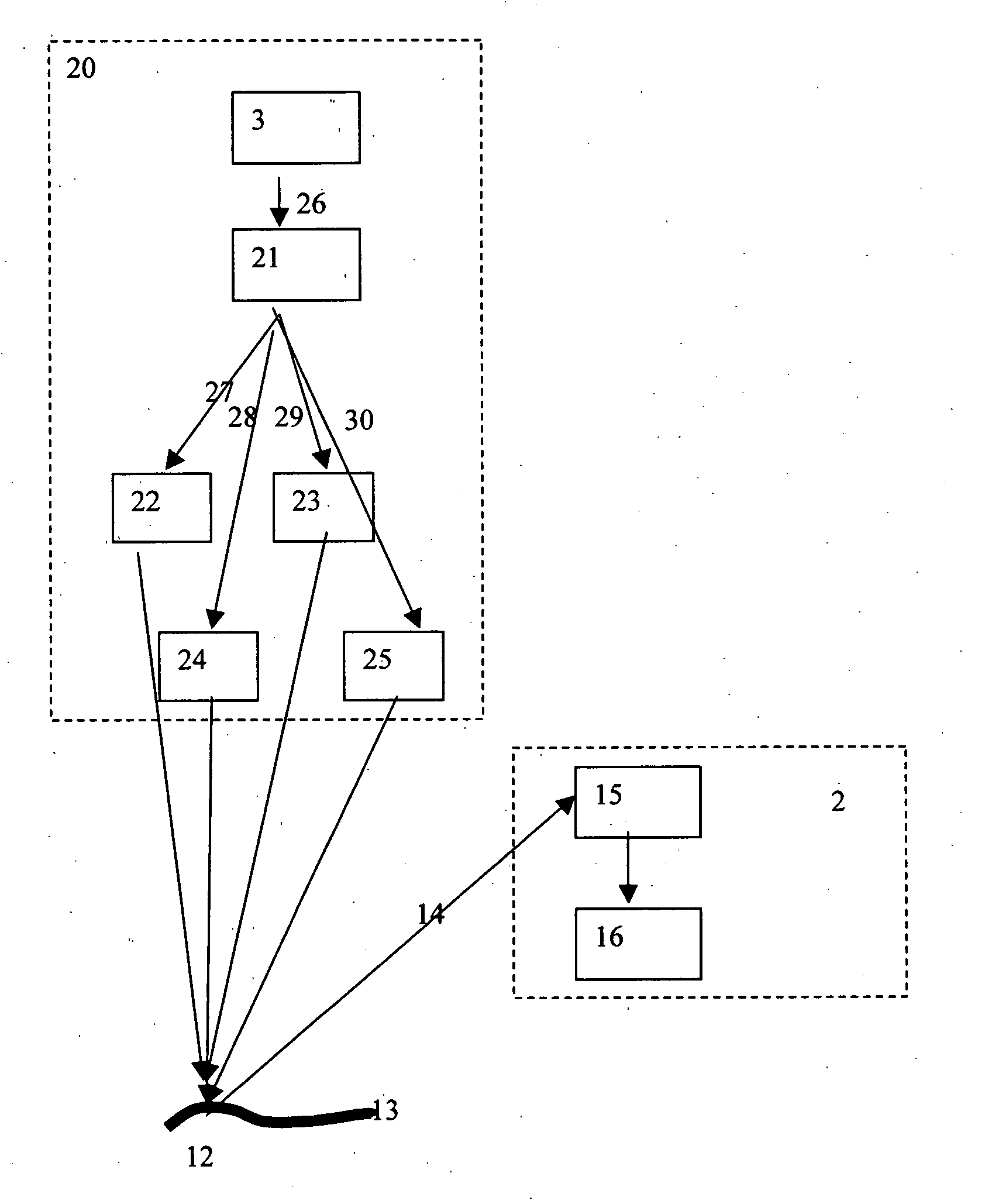
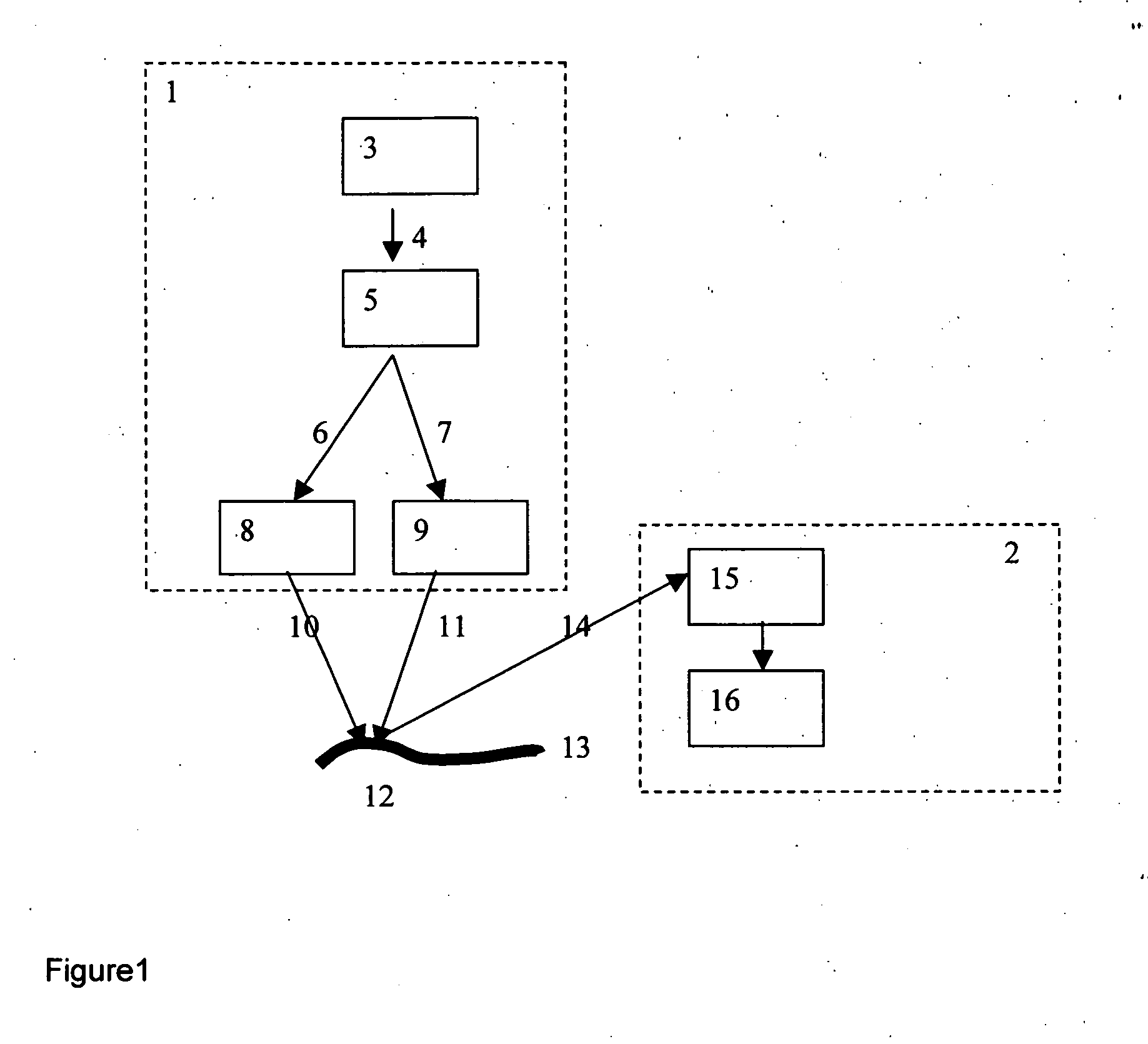
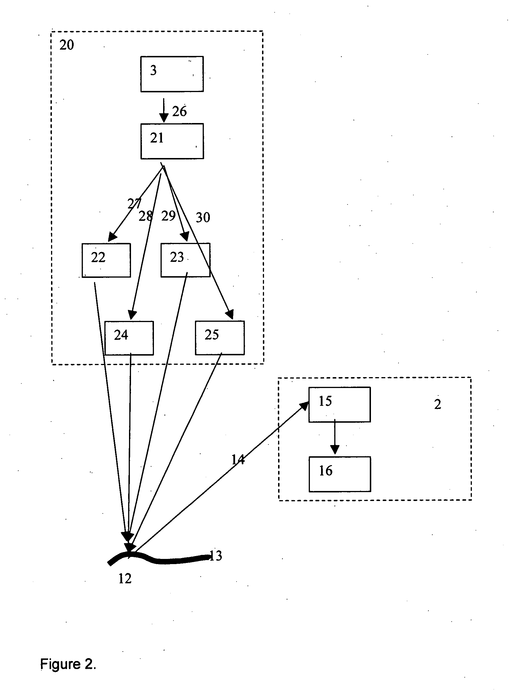
[0021] In one embodiment of the present invention, an optical device is provided, the block diagram of which is shown in FIG. 1, where 1 is a unit that combines elements for interrogated surface illumination, while 2 is the unit for a signal detection and information on vibration recovery block. The system operates as follows: the light source 3 outputs the beam 4 splitted by a splitter 5 into two beams 6 and 7. The light source 3, preferably a laser, generates beam at least one wavelength from in the UV or visible or near infrared or far infrared ranges (from 0.2 nm to 20 μm). The beams 6 and 7 impinge the beam directing devices 8 and 9. These beam directing devices are selected from, a mechanical devices, a mirror on gimbals and a MEMS devices. Beam directing devices enable to perform two functions: (1) target the beams on the particular spot on the interrogated surface; (2) scan the beams over the interrogated surface.

[0022] Output beams 10 and 11 are directed on the same spot 1...


PUM


Abstract

An optical system provides information about tangential vibration components of a surface at remote location. The optical system includes a light source assembly that emits first and second beams, each having one or more wavelengths and one or two polarizations. The first and second beams are directed to the interrogated surface. A detector system is positioned to detect a third beam formed by at least a portion of the first and second beams being reflected from the interrogated surface. The first, second and third beams having incident and reflection angles relative to the interrogated surface that do not lay in a same plane. The detector system positioned remotely from the interrogated surface, and providing information on a phase change in the third beam relative to the first and second beam. The phase change is indicative of at least one surface vibration vector component of the interrogated surface. The detector system is a 90 degree optical hybrid balanced detector with four photodiodes.

Description

CROSS-REFERENCE TO RELATED APPLICATIONS [0001] This application claims the benefit of U.S. Ser. No. 60 / 543,065, filed Feb. 9, 2004. This application is also a continuation-in-part of U.S. Ser. No. 10 / 669,130, filed Sep. 22, 2003. Both of the above applications are fully incorporated herein by reference.FIELD OF INVENTION [0002] This invention relates generally to the systems and methods for measuring vibration frequency of an interrogated surface, and more particularly to systems and methods for measuring vibration frequency in three dimensions in response to optical signal detection. BACKGROUND OF THE INVENTION [0003] The principles of Doppler Laser vibrometry are well known to the person skilled in the art, the general description can be found for example at the web site of Polytec company, CA: http: / / www.polytec.com / int / 158—1004.asp?highlightSubMenu=Vibrometer%20University &highlightPopupMenu=Signal%20Processing, the entire content of which is incorporated by reference herein. Vi...

Claims


Application Information

Patent Timeline
IPC IPC(8): G01B9/02
CPCG01H9/004G01H9/00
Inventor SHPANTZER, ISAACSALAMON, AVIVCHO, PAK SHING
Owner CELIGHT
Why Eureka
Try Eureka