Multilayered oscillating device with spine support

a multi-layered, spine support technology, applied in the direction of microelectromechanical systems, dynamo-electric machines, instruments, etc., can solve the problems of limited oscillating speed, reduced print speed, added mass, etc., to reduce the material of the spine structure, reduce the mass and weight of the device, and reduce the weight and mass

Active Publication Date: 2005-08-25
TEXAS INSTR INC
View PDF4 Cites 17 Cited by
  • Summary
  • Abstract
  • Description
  • Claims
  • Application Information

AI Technical Summary

Benefits of technology

[0014] To reduce the mass and weight of the device, the attaching member of the hinge layer and a back portion of the front or operational layer are formed to define one or more spines that extend from the pivot axis at the center of the device to the ends of the long edges of an elongated ellipse-shaped mirror functional surface. The spine(s) may be formed by controlled deposition, or by etching or removing mate

Problems solved by technology

Using only one of the sweep directions of the mirror, of course, reduces the print speed.
Furthermore, the magnets mounted on the functional surface of the device portion added mass and limited the oscillating speed.
Unfortunately, the added mass of the magnets becomes more and more of a problem as the required frequency increases to meet higher and higher operational speeds.
Unfortunately, such elongated elliptical-shaped devices, such as a mirror, introduce inertia forces that

Method used


Image

  • Multilayered oscillating device with spine support
  • Multilayered oscillating device with spine support
  • Multilayered oscillating device with spine support

Examples


Embodiment Construction

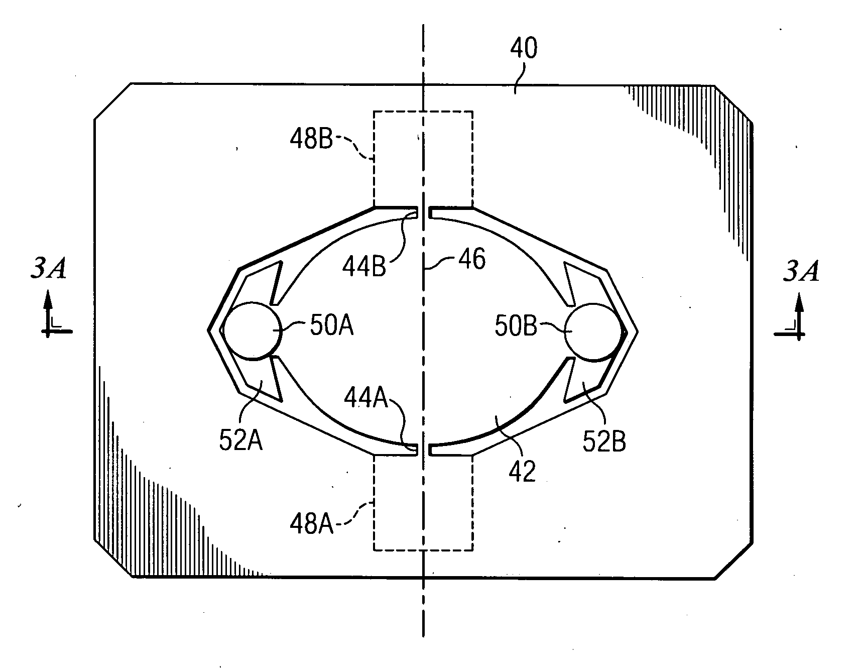
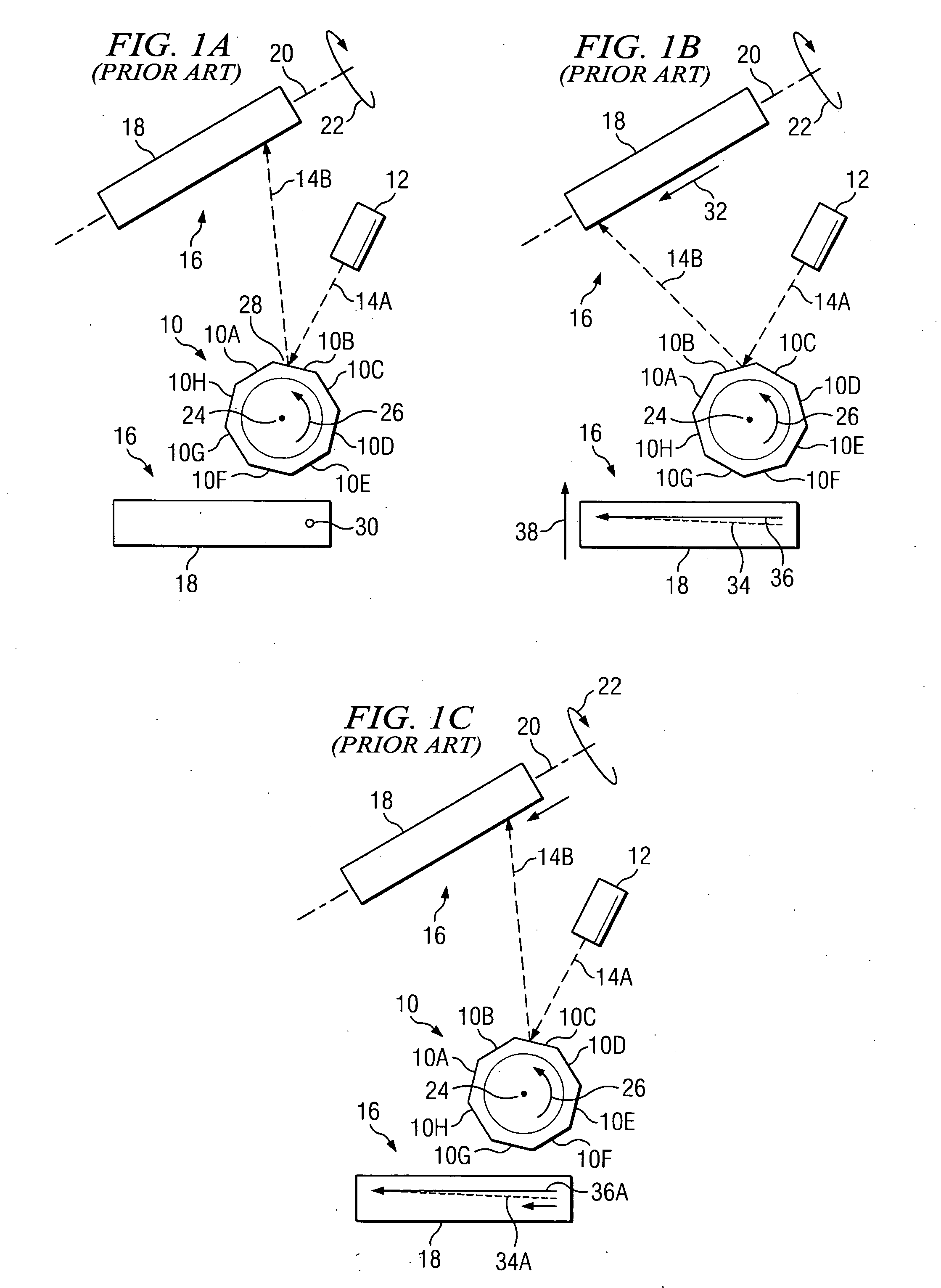
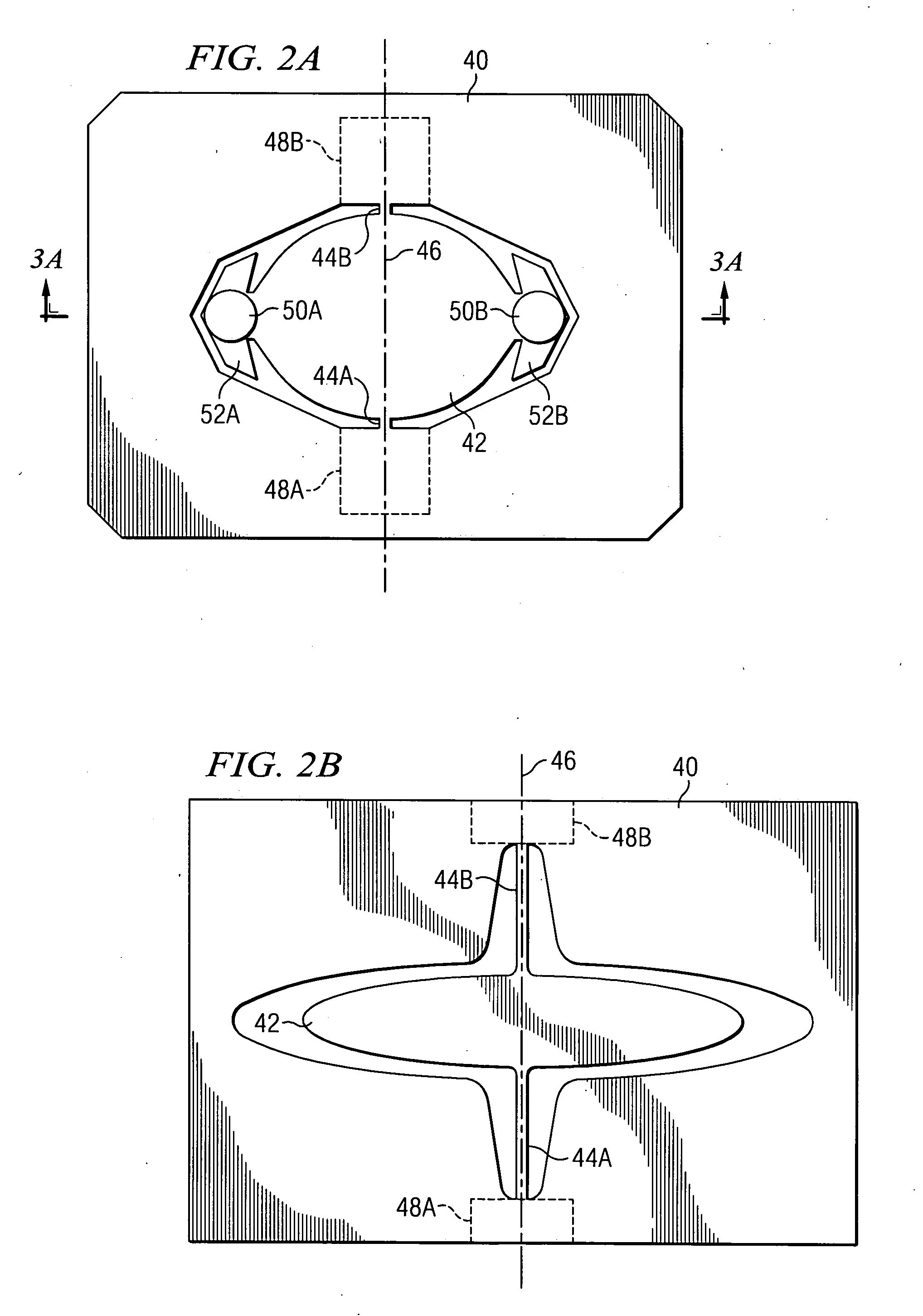
[0034] Like reference numbers in the figures are used herein to designate like elements throughout the various views of the present invention. The figures are not intended to be drawn to scale and in some instances, for illustrative purposes, the drawings may intentionally not be to scale. One of ordinary skill in the art will appreciate the many possible applications and variations of the present invention based on the following examples of possible embodiments of the present invention. The present invention relates to a high-speed pivoting device with a moveable functional surface. Various functional surfaces may be suitable for use with the invention. For example, a reflective surface or mirror is particularly suited for use as the functional surface and may be used to provide the raster scans for laser printers and displays or high-speed optical switching. More specifically, the invention relates to a pivoting structure and magnetic drive for maintaining high speed resonant pivo...


PUM


Abstract

A multilayered torsional hinged device such as a scanning mirror including a hinge layer with an attaching member pivotally supported by torsional hinges. A front layer is bonded to the front side of the attaching member and a back layer is bonded to the back side of the attaching member. The front layer and the back layer have equal mass moments to balance the moment of inertia and stresses on the torsional hinges. Further, the attaching member and a back portion of the front layer define a spine structure that extends to the tips of the mirror. The spine structure allows reduction of weight and mass of the mirror while maintaining mirror stiffness. The back layer may be a permanent magnet if the mirror oscillating drive is a magnetic drive. Alternately, the back layer may be another silicon slice.

Description

[0001] This application claims the benefit of U.S. Provisional Application No. 60 / 424,915 filed on Nov. 8, 2002, entitled “Composite MEMS Micromirror Structure for High Frequency Operation Without Dynamic Deformation,” which application is hereby incorporated herein by reference. CROSS-REFERENCE TO RELATED APPLICATIONS [0002] This application relates to the co-pending and commonly assigned patent application Ser. No. ______, entitled “Multilayered Oscillating Functional Surface,” (Attorney Docket TI-35578) filed concurrently herewith, which application is hereby incorporated herein by reference.TECHNICAL FIELD [0003] The present invention relates generally to rapidly pivoting multilayered MEMS (micro-electric mechanical systems) torsional hinge devices, and more specifically to high-speed pivoting mirrors, including scanning mirrors operating at a resonance frequency. A hinge layer having a first set of torsional hinges for providing the back and forth pivoting at a controlled frequ...

Claims


Application Information

Patent Timeline
IPC IPC(8): G02B26/08G02B26/10H02K33/00
CPCB81B3/007G02B26/105G02B26/0833B81B2201/042
Inventor ORCUTT, JOHN W.
Owner TEXAS INSTR INC
Why Eureka
Try Eureka