Image forming apparatus

Active Publication Date: 2005-08-25
SHARP KK
View PDF1 Cites 4 Cited by
  • Summary
  • Abstract
  • Description
  • Claims
  • Application Information

AI Technical Summary

Benefits of technology

[0035] With the above-described aspect of the present invention, between the plate between the oscillation member and the elastic member is subjected to amplitude movement in the inclination direction or a direction perpendicular to the inclination direction, and developer that drops onto the plate is made to actively flow along the inclination such that it is possible to even more effectively prevent accumulation of developer on the plate.
[0036] Further still, in the above-described aspect of the present invention, below a lower end in inclination direction of the transparent plate, a receiving member is provided for collecting developer that drops on a surface of the transparent plate on the image carrier side and flows along an inclination. In this case, it is possible to quickly collect in the receiving member the developer that has dropped on the plate such that adherence of smearing by the developer inside the image forming apparatus is suppressed as m

Problems solved by technology

In this way, the optical unit for exposure positioned below the development unit may be soiled by developer, which tends to cause reduced printing quality by disturbing the written image or damaging the polygon mirrors that rotate at high speed, as well as smearing the fθ lens and the plurality of mirrors.
However, since the optical path from the optical unit for exposure cannot be blocked in order to write image information to the photosensitive body, it is necessary to leave an aperture portion at the portion where the optical path is incident, and this results in ingression of developer from the aperture portion into the optical unit for exposure.
However, with an apparatus such as that mentioned above, which is provided with an openable-closeable shutter at the portion (aperture portion) where the optical path crosses from the optical unit such as the optical unit for exposure, there is uncertainty as to whether or not the shutter mechanism can properly fulfill its function in regard to the operation of the apparatus.
For this reason, when the shutter is in an open state, it is unable to block the dropped/spattered develo

Method used


Image

  • Image forming apparatus
  • Image forming apparatus
  • Image forming apparatus

Examples


Example

[0042] Hereinafter, embodiments of the present invention will be described with reference to the accompanying drawings. The present embodiment is described regarding a case in which the present invention is applied to a color printer.

[0043] Description of the Overall Configuration of the Image Forming Apparatus

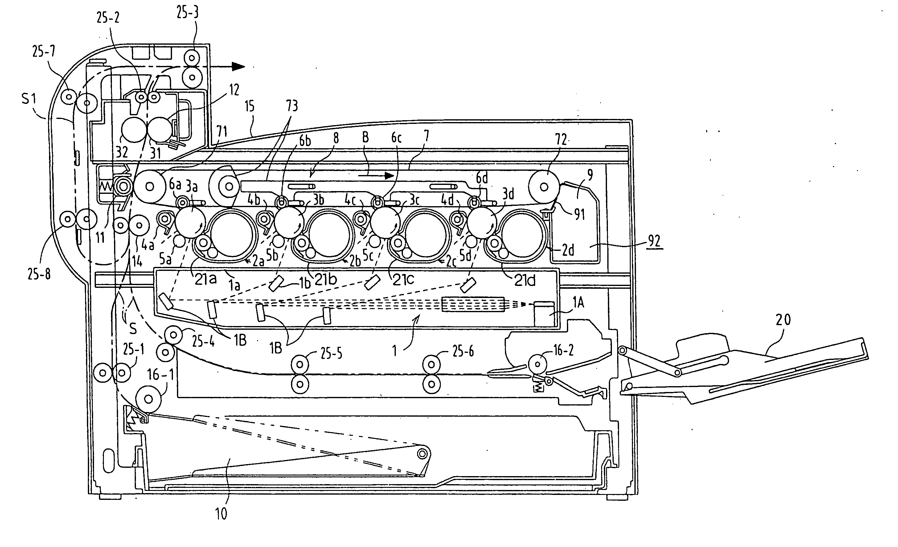
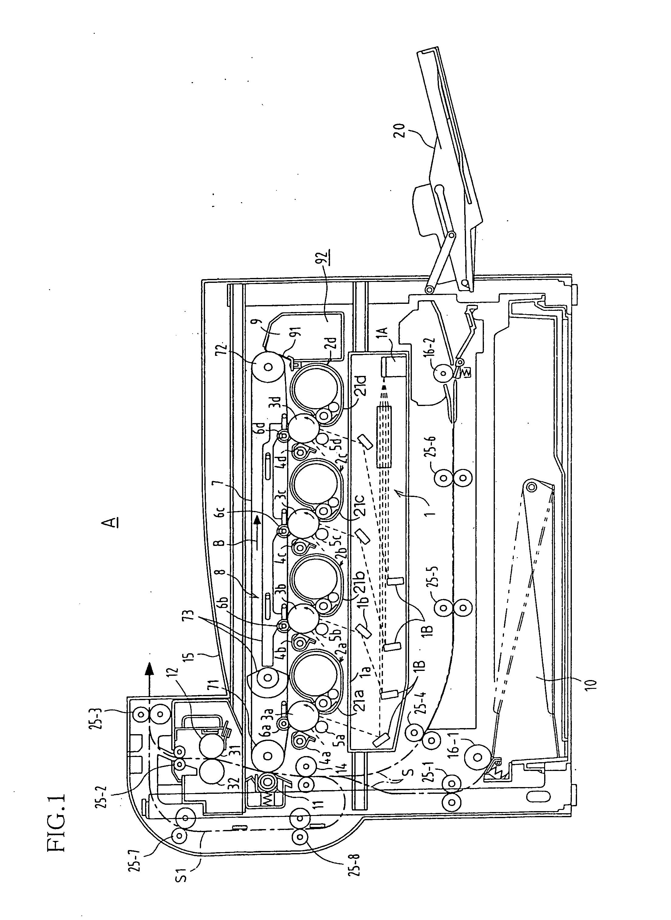
[0044]FIG. 1 shows an outline of the internal configuration of an image forming apparatus A according to the present embodiment. In response to image data transmitted from an external portion (a terminal device such as a personal computer for example), the image forming apparatus A forms a multicolor (full color) image or a single color (monochrome) image on a predetermined sheet (sheet of recording paper). As shown in FIG. 1, the image forming apparatus A is configured provided with an exposure unit 1, a development apparatus 2 (2a to 2d), a photosensitive drum 3 (3a to 3d) as an image carrier, a charger 5 (5a to 5d), a cleaner unit 4 (4a to 4d), an intermediate transfer be...


PUM


Abstract

In an image forming apparatus in which positioned below a development unit for accommodating a toner is an exposure unit that writes to a photosensitive drum by exposing an electrostatic latent image, an aperture portion on an upper surface of an exposure unit case positioned in an optical path of light from the exposure unit is provided so as to not become an impediment to the optical path of the light and a glass plate is inclined and provided on the aperture portion. An inclination angle of the glass plate is set to an angle inclined 40° with respect to a horizontal line so as to be greater than a repose angle of the toner when the toner has poor fluidity under a condition of high temperature and high humidity.

Description

CROSS REFERENCE TO RELATED APPLICATIONS [0001] This application claims priority under 35 U.S.C. § 119(a) on Patent Application No. 2004-46550 filed in Japan on Feb. 23, 2004, the entire contents of which are hereby incorporated by reference. BACKGROUND OF THE INVENTION [0002] 1. Field of the Invention [0003] The present invention relates to electrophotographic image forming apparatuses such as printers that are devised so as to prevent smearing of the exposure unit due to natural dropping of the developer and spattering of the developer, and particularly relates to measures for preventing soiling on the optical path of light that is exposed from exposure units. [0004] 2. Description of the Related Art [0005] Conventionally, the layout of the paper-supply unit, printing unit, paper-discharge unit, and optical units (there are two types, an optical unit for reading manuscripts for printing and an optical unit for exposure that writes the image information that has been read to an elec...

Claims


Application Information

Patent Timeline
IPC IPC(8): G03C8/00B41J2/44G03G15/04G03G21/00
CPCG03G15/04045G03G2215/06
Inventor MORIMOTO, SHIGENORITAKAI, YASUHIROUEDA, ATSUSHINARIKIYO, TAKAHISA
Owner SHARP KK
Why Eureka
Try Eureka