Z-pin closeout joint and method of assembly

a technology of closeout joints and components, applied in the direction of weaving, transportation and packaging, layered products, etc., can solve the problems of reducing the production efficiency of layered products, requiring expensive and time-consuming drilling and fastening operations, and weakening the structure, so as to achieve a larger dimensional tolerance and strong joint

Inactive Publication Date: 2005-08-25
LOCKHEED MARTIN CORP
View PDF4 Cites 15 Cited by
  • Summary
  • Abstract
  • Description
  • Claims
  • Application Information

AI Technical Summary

Benefits of technology

[0010] A method uses a three-dimensional, adhesive-infused, woven preform to assemble two components, each component having z-pins extending from bonding surfaces. The woven perform has a thickness at least equal to the sum of the lengths of the protruding portions of the z-pins. The components and preform are assembled with surfaces of the preform contacting surfaces of the components, the z-pins penetrating into the preform. The adhesive in the preform is then cured, adhering the preform to the components and retaining the z-pins within the preform. The adhesive may be cured at room temperature or through heat applied to the outer component. Alternatively, an electron-bearn may be used to cure the adhesive. Use of z-pins in the bond area and an adhesive, instead of a resin, creates a stronger joint, especially with fiber-reinforcement of the adhesive. The thickness of the compressible, three-dimensional weave provides for a larger dimensional tolerance at each bond line.

Problems solved by technology

Closeout panels can present problems for manufacturers, in that panels may attach to a substructure without access to the backside of the panel.
These methods require expensive and time-consuming drilling and fastening operations and may weaken the structure: More recently, these panels have been co-bonded or secondarily bonded using resin or a thin layer of adhesive.
Because of the inferior bonding characteristics of laminating resins, a thin layer of adhesive is often placed between the preform and the components.
Generally, an adhesive film is used, which is expensive and adds to fabrication time.
Methods for ensuring proper bonding may include tools, such as molds or vacuum bags, but particular applications may prevent the use of tools due to the inaccessibility of one or both sides of the joint.

Method used


Image

  • Z-pin closeout joint and method of assembly
  • Z-pin closeout joint and method of assembly
  • Z-pin closeout joint and method of assembly

Examples


Embodiment Construction

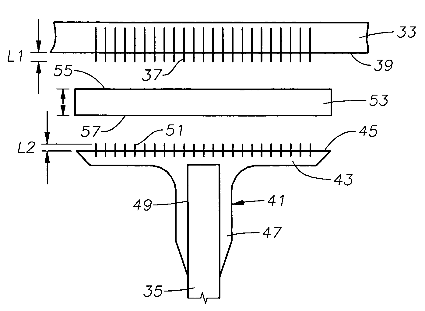
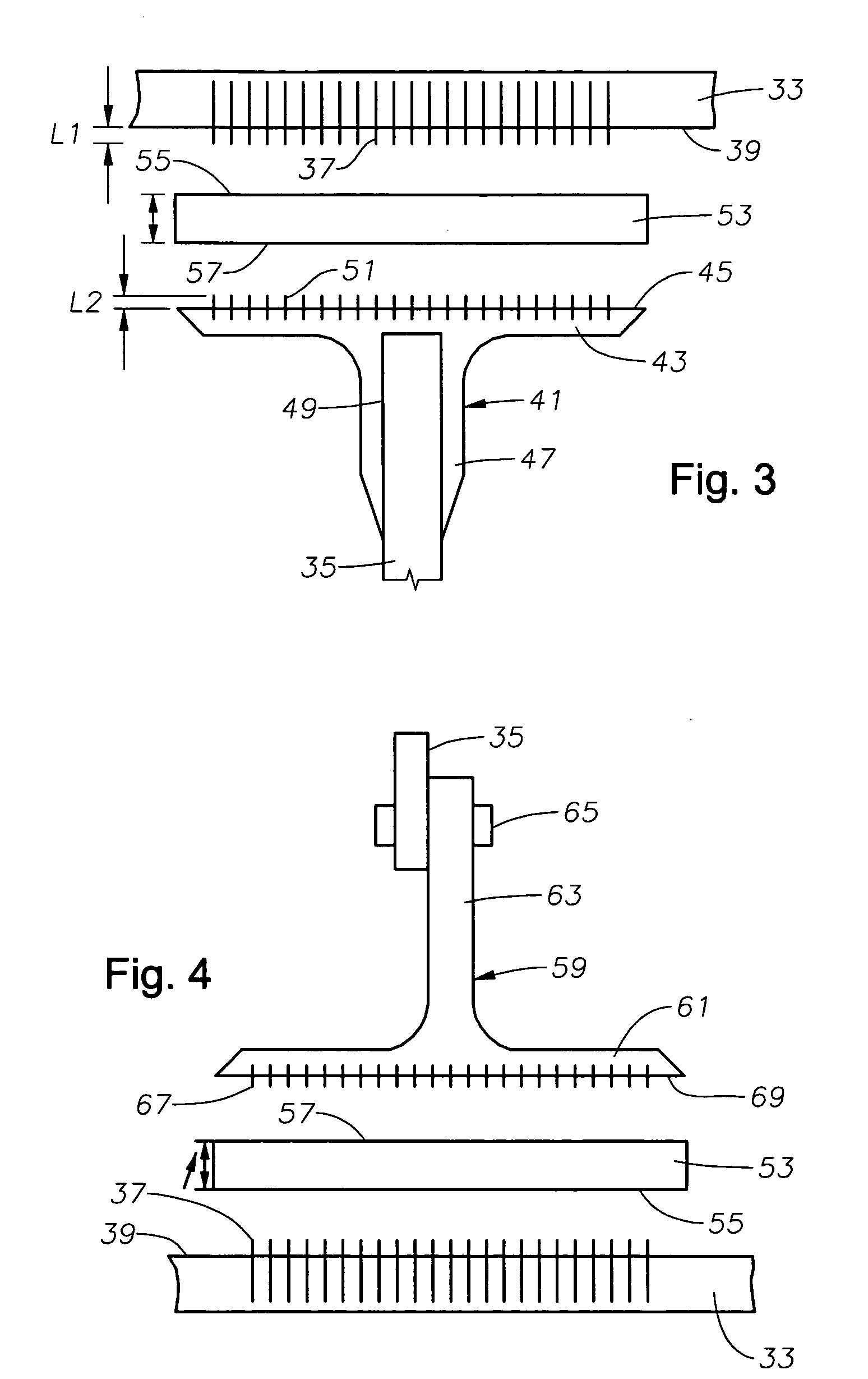
[0017]FIGS. 3 and 4 illustrate preferred embodiments of assemblies using an adhesive-infused, three-dimensional (3-D), woven textile preform used for assembling parts into structural joints. The preferred adhesive is FM® 300, also available from Cytec Industries, Inc., but other adhesives will work, providing the adhesive can be infused in a way that properly “wets out,” or saturates, the fiber bundles in the preform.

[0018] Various resin systems are sold under the terms “laminating resins” and “adhesives,” though there is no “bright-line,” industry-standard definition by which to distinguish one from the other. The term “adhesive,” as used herein, is meant as a resin system that has a lower modulus of elasticity and / or a higher strain-to-failure than the resin forming the matrix of the parts to be adhered. The combination of these characteristics is described as higher toughness, and adhesives have a higher toughness than laminating resins, which tend to be more brittle and have lo...


PUM

PropertyMeasurementUnit
tensile strengthaaaaaaaaaa

Abstract

A method uses a three-dimensional, adhesive-infused, woven preform to assemble two components, each component having z-pins extending from bonding surfaces. The components and preform are assembled with surfaces of the preform contacting surfaces of the components, the z-pins penetrating into the preform. The perform is equal or slightly greater in thickness than the protrusion lengths of the z-pins. The adhesive in the preform is then cured, adhering the preform to the components and retaining the z-pins within the preform.

Description

CROSS-REFERENCE TO RELATED APPLICATION [0001] This application is a continuation-in-part of application Ser. No. 10 / 212,339, filed Aug. 5, 2002.FIELD OF THE INVENTION [0002] This invention generally relates to assembly of components using woven preforms and particularly relates to assembly of components in closeout joints using adhesive-infused preforms. BACKGROUND OF THE INVENTION [0003] Closeout panels can present problems for manufacturers, in that panels may attach to a substructure without access to the backside of the panel. In the past, these panels have been bolted to the substructure or attached using blind fasteners, such as pull rivets. These methods require expensive and time-consuming drilling and fastening operations and may weaken the structure: More recently, these panels have been co-bonded or secondarily bonded using resin or a thin layer of adhesive. [0004] Typically, laminating resins are used as the matrix material in woven textiles, this also being true for wov...

Claims


Application Information

Patent Timeline
Patent Type & Authority Applications(United States)
IPC IPC(8): B29C65/00C09J5/06
CPCB29C65/562B29C65/564B29C66/474Y10T428/24174C09J5/06B29C66/472Y10T428/28B29C66/721B29C66/1122B29C66/72141B29C66/73161Y10T442/2738
Inventor BERSUCH, LARRY R.SHEAHEN, PATRICK D.
Owner LOCKHEED MARTIN CORP
Why Eureka
Try Eureka