Dynamic contrast enhanced imaging using a mamillary distributed parameter model

a distributed parameter and dynamic contrast technology, applied in the field of medical imaging, can solve the problems of inability to resolve microscopic disease, inability to predict clinical outcome, overlap between malignant and benign inflammatory tissue,

Inactive Publication Date: 2005-08-25
NANYANG TECH UNIV
View PDF6 Cites 9 Cited by
  • Summary
  • Abstract
  • Description
  • Claims
  • Application Information

AI Technical Summary

Benefits of technology

[0013] These models and methods may be used in otherwise conventional DCE imaging systems, or embodied in software.

Problems solved by technology

While current DCE imaging techniques are in clinical use, they have numerous limitations, including overlap between malignant and benign inflammatory tissue, failure to resolve microscopic disease, and the inconsistent predictive value of enhancement pattern with regard to clinical outcome.
In part, some of these limitations are attributable to the pharmacokinetic models used in current DCE imaging techniques.

Method used


Image

  • Dynamic contrast enhanced imaging using a mamillary distributed parameter model
  • Dynamic contrast enhanced imaging using a mamillary distributed parameter model
  • Dynamic contrast enhanced imaging using a mamillary distributed parameter model

Examples


Embodiment Construction

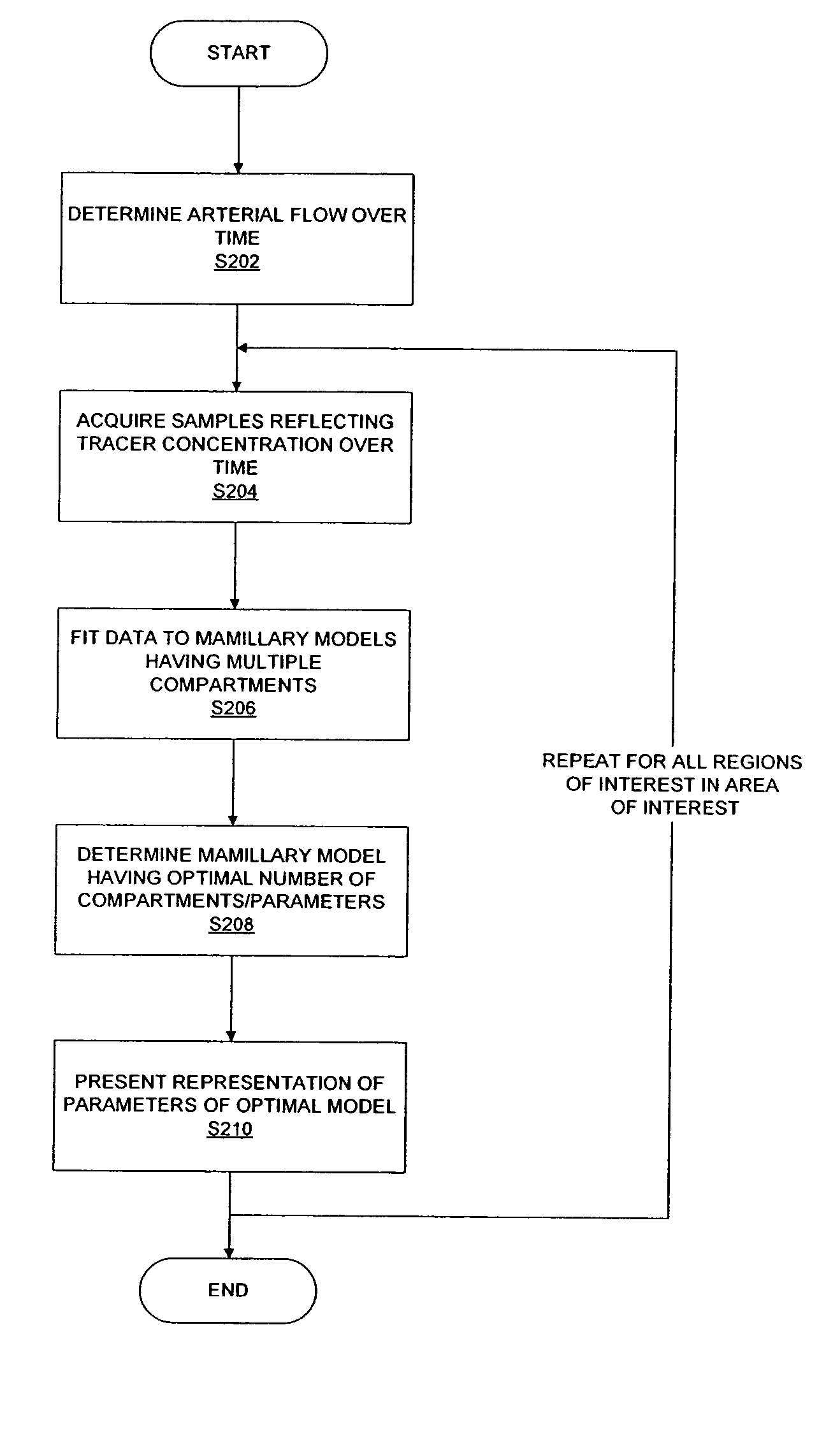
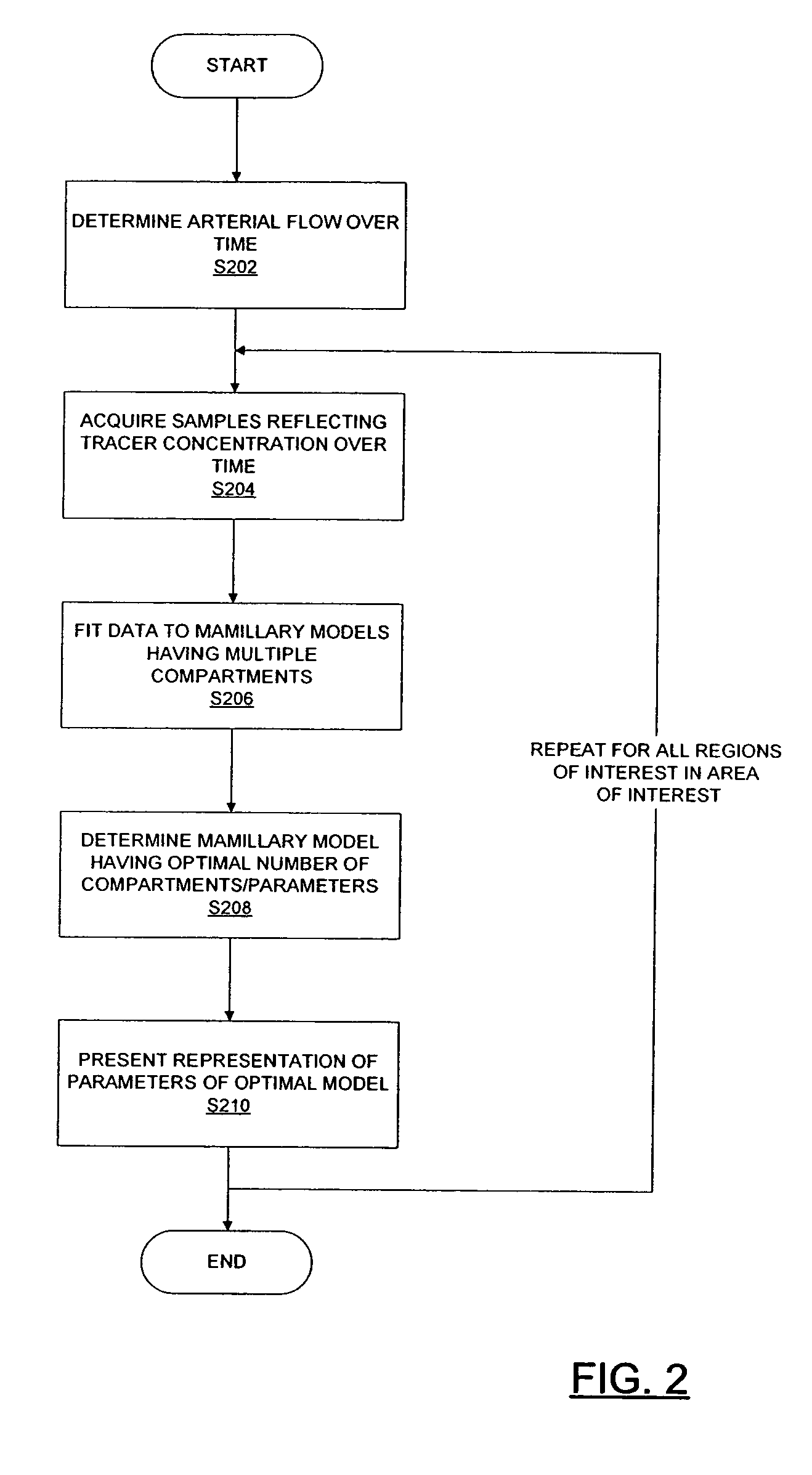
[0022] As noted, DCE imaging typically involves the intravenous introduction of a contrast medium (or tracer) in the fluid blood stream and subsequent sequential imaging to simultaneously monitor the course of the tracer concentration in the tissue in a region of interest and the feeding artery (or fluid source) over time.

[0023] For example, for CT imaging, tracer concentration in a region of interest can be estimated by averaging the sensed concentration in a region of interest. For example, the tracer used in CT imaging is commonly iodine based. In the CT image, the intensity value is directly proportional to the concentration of tracer. For MRI, other techniques may be employed: known transforms correlate image intensity and tracer concentration.

[0024] Mathematically, a relationship between tracer flow in the tissue Ctiss(t) at a region of interest, and the feeding artery Ca(t) can be derived by assuming a causal, linear time-invariant (LTI) system. The response of the system (...


PUM


Abstract

A method of dynamic contrast enhanced (DCE) imaging includes: for a region of interest, sampling the concentration of a tracer liquid in a fluid over a time interval to arrive at a plurality of samples; fitting the plurality of samples to a plurality of multi-compartment mamillary pharmacokinetic models, each of the plurality of models modelling fluid flow in a number of interstitial compartments about a central compartment at the region interest, as a result of flow caused by a source of the fluid, so as to determine a plurality of fitting parameters for each of the plurality of models; determining a preferred one of the plurality of models; and presenting indicators indicative of values of the plurality of parameters for the preferred one of the models. Numerous multi-compartment mamillary pharmacokinetic models are disclosed. The models and methods may be used in DCE imaging systems and software.

Description

FIELD OF THE INVENTION [0001] The present invention relates generally to medical imaging, and more particularly to dynamic contrast enhanced imaging, using a mamillary distributed parameter model. BACKGROUND OF THE INVENTION [0002] In recent years, numerous new medical imaging techniques have been introduced, and have advanced significantly. Techniques such as magnetic resonance imaging (MRI), computed tomography (CT), ultrasound, radio isotope imaging, and electrical impedance tomography have joined conventional x-ray imaging. [0003] Dynamic contrast-enhanced magnetic (DCE) imaging is based on the acquisition of images, using for example MRI or CT scanning, in the presence of a contrast medium. [0004] Typically, images in a region of interest over a time interval before, during, and after the administration of a contrast medium are acquired. Acquired data is then fitted to pharmacokinetic models from which parameters based on the rates of fluid exchange can be calculated, as for ex...

Claims


Application Information

Patent Timeline
Patent Type & Authority Applications(United States)
IPC IPC(8): A61B6/00
CPCA61B6/507A61B6/481
Inventor KOH, TONG SANDENNIS CHEONG, LAI HONG
Owner NANYANG TECH UNIV
Why Eureka
Try Eureka