
Detecting electromechanical oscillations in power systems

Active Publication Date: 2005-08-25
HITACHI ENERGY SWITZERLAND AG
View PDF9 Cites 41 Cited by
  • Summary
  • Abstract
  • Description
  • Claims
  • Application Information

AI Technical Summary

Benefits of technology

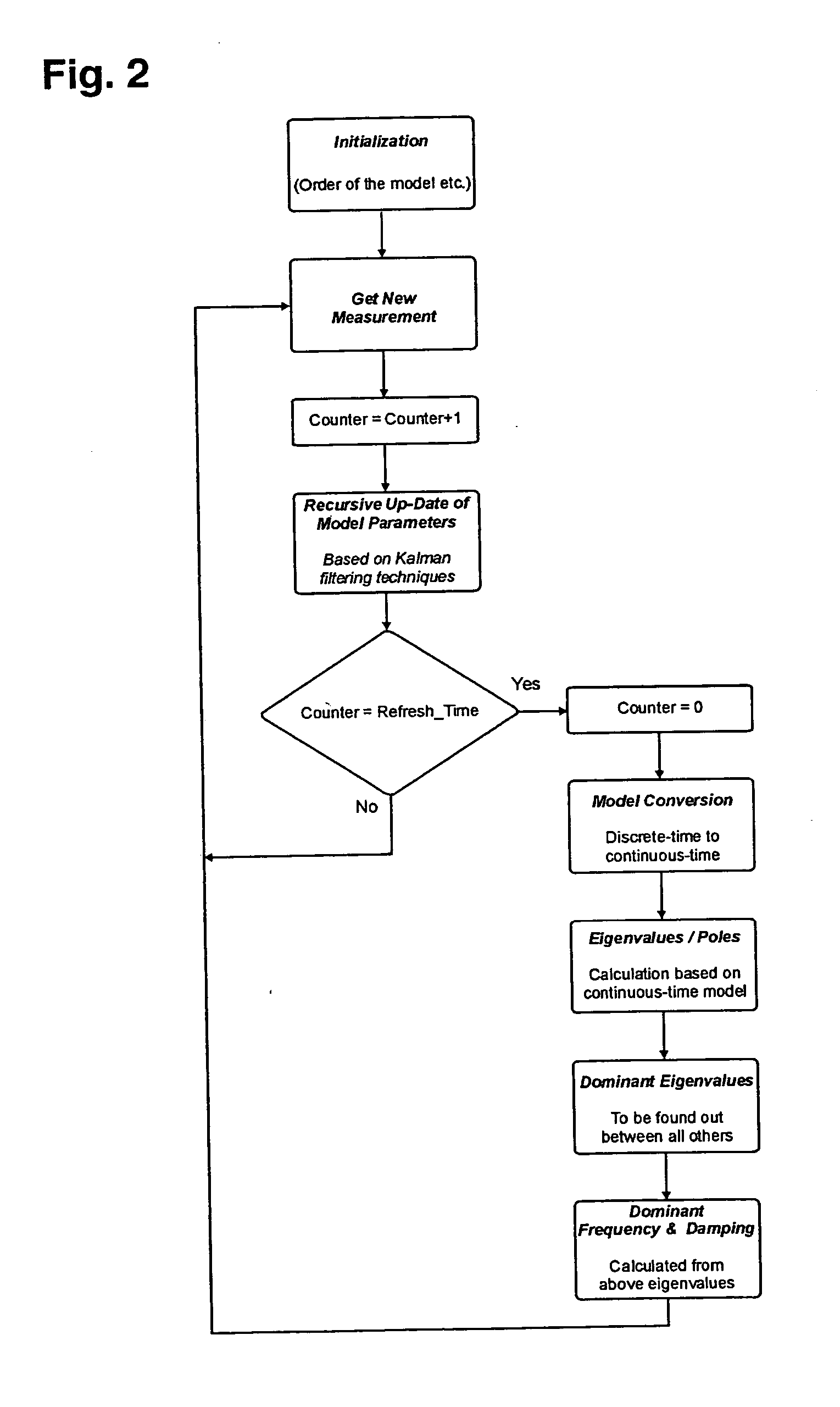
[0009] In a preferred variant of the proposed approach, the parameters of the parametric model which fit best the measured values of the system quantity are estimated subject to an optimization criterion. Further, the model is assumed to predict the next sampled value of the system quantity, based on a time series containing a linear combination of a finite number of n previous measured values. Such a model is called linear autoregressive, with the integer n denoting its dynamical order as well as the number of parameters to be estimated. It has the advantage of the simple form of a linear difference equation containing only n parameters and additionally is suitable to represent frequency spectra with narrow peaks.

Problems solved by technology

As a consequence of the competition between utilities and the emerging need to optimize assets, substantially increased amounts of power are transmitted through the existing networks, invariably causing transmission bottlenecks and oscillations of parts of the power transmission systems.
Since moments of inertia of the generators also come into play, this results typically in speed over-corrections and the whole system or a part thereof starts swinging in the same manner as a set of interconnected pendulums.
However, an increase in the transmitted power of a few MWs may make the difference between stable oscillations and unstable oscillations which have the potential to cause a system collapse or result in lost of synchronism, lost of interconnections and ultimately the inability to supply electric power to the customer.
However there is no warning to the transmission operator if a new operating condition causes the abovementioned oscillatory modes to become lightly damped and thus potentially dangerous.
Due to the batch sampling technique, no on-line or real-time analysis of the power system was possible.

Method used


Image

  • Detecting electromechanical oscillations in power systems
  • Detecting electromechanical oscillations in power systems
  • Detecting electromechanical oscillations in power systems

Examples


Embodiment Construction

[0007] It is therefore an objective of the invention to enable an operator of an electric power transmission network to identify in real-time electromechanical oscillations. This objective is achieved by a method, system and computer program for detecting electromechanical oscillations in power systems according to claims 1, 9 and 10. Further preferred embodiments are evident from the dependent patent claims.

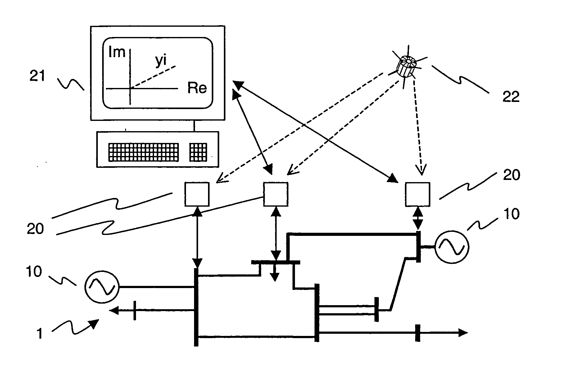
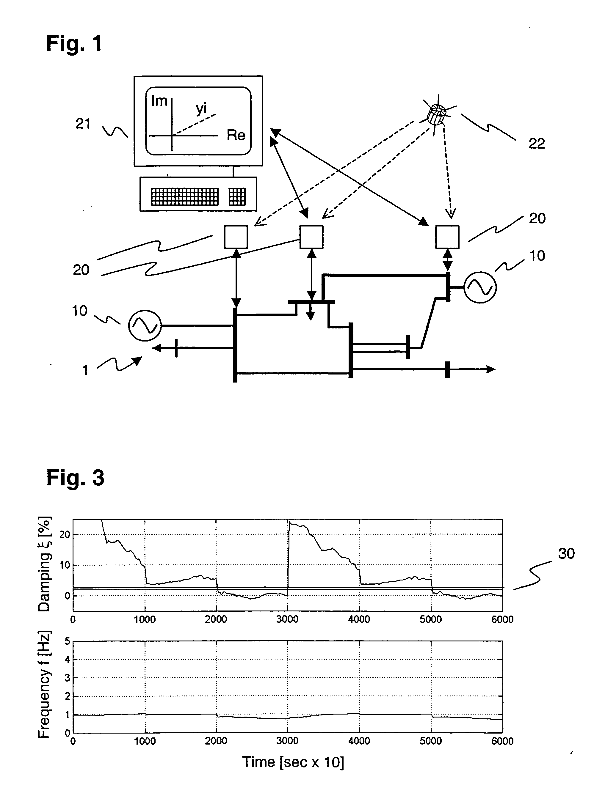
[0008] According to the invention, a system quantity or signal such as e.g. amplitude or angle of the voltage or current at a selected node of the network is sampled, i.e. measured at discrete time intervals, and a series comprising several of the measured values of said system quantity is generated. From this series, the parameters of a parametric model representing the behaviour of a power transmission system, or a particular aspect thereof, are estimated. This process is carried out in an adaptive manner, i.e. every time a new value of the system quantity is measured, the pa...


PUM


Abstract

The detection of electromechanical oscillations in power systems and the estimation of their parameters (frequency ƒ and damping ξ) is based on a linear time-varying model. The parameters of the linear model are on-line adapted by means of Kalman filtering techniques to approximate the measured signal y (representing the behaviour of the power system) optimally in the sense of a quadratic criterion. The estimated model parameters are then the basis for the calculation of parameters of the oscillations. Adaptive algorithms are based on a recursive calculation of the estimated parameter vector for each time-step based on the new value of the measured signal and the old values of the estimated parameters. As opposed to the collection of data over a time window and then performing the parameter identification at once, any change in the system can thus be detected much faster.

Description

FIELD OF THE INVENTION [0001] The invention relates to the field of electric power transmission networks interconnecting a plurality of generators. It departs from a method for detecting electromechanical oscillations in power systems as described in the preamble of claim 1. BACKGROUND OF THE INVENTION [0002] In the wake of the recent and still ongoing deregulations of the electric power markets, load transmission and wheeling of power from distant generators to local load consumers has become common practice. As a consequence of the competition between utilities and the emerging need to optimize assets, substantially increased amounts of power are transmitted through the existing networks, invariably causing transmission bottlenecks and oscillations of parts of the power transmission systems. [0003] Interconnected alternating current generators remain in synchronism because of the self-regulating properties of their interconnection. Hence, if a first generator deviates from its syn...

Claims


Application Information

Patent Timeline
IPC IPC(8): H02J3/24
CPCH02J3/24Y04S10/265Y02E60/728Y02E60/00Y04S10/00Y04S10/22Y02E40/70H02J3/242
Inventor KORBA, PETRLARSSON, MATSREHTANZ, CHRISTIAN
Owner HITACHI ENERGY SWITZERLAND AG
Learn More