
Engine control device

a control device and engine technology, applied in the direction of electric control, machines/engines, mechanical equipment, etc., can solve the problems of increasing the cost of the engine, consuming extra space, and adding additional components, so as to prevent the engine from surging, reduce the cost, and avoid undesirable secondary effects

Active Publication Date: 2005-09-01
NISSAN MOTOR CO LTD
View PDF9 Cites 9 Cited by
  • Summary
  • Abstract
  • Description
  • Claims
  • Application Information

AI Technical Summary

Benefits of technology

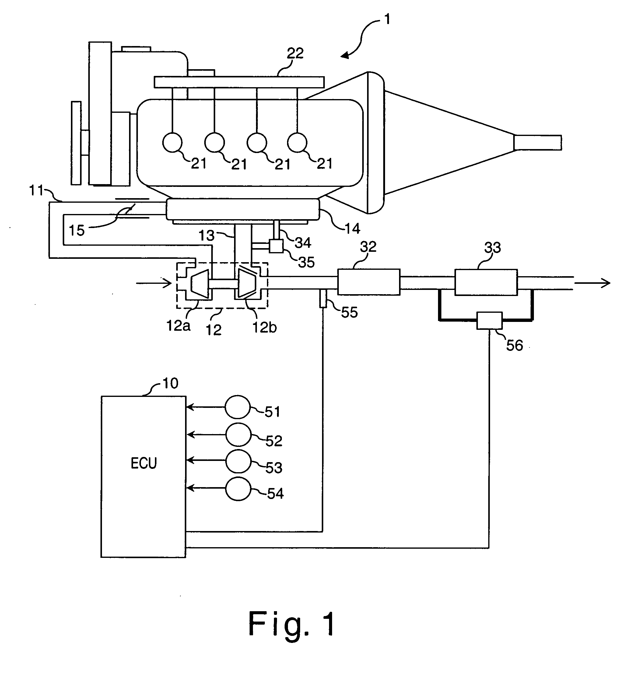
[0012] The present invention was contrived in view of the foregoing. One object of the present invention is to prevent surging in an engine equipped with both a turbocharger and an EGR device while curbing costs by utilizing existing equipment and avoiding undesirable secondary effects.

Problems solved by technology

The additional components inflate the cost of the engine and consume extra space, which is particularly troublesome in the case of passenger vehicles having little available space.

Method used


Image

  • Engine control device
  • Engine control device
  • Engine control device

Examples


second embodiment

[0071] Referring now to FIG. 10, an operating state detecting section in accordance with a second embodiment will now be explained. In view of the similarity between the first and second embodiments, the parts of the second embodiment that are identical to the parts of the first embodiment will be given the same reference numerals as the parts of the first embodiment. Moreover, the descriptions of the parts of the second embodiment that are identical to the parts of the first embodiment may be omitted for the sake of brevity.

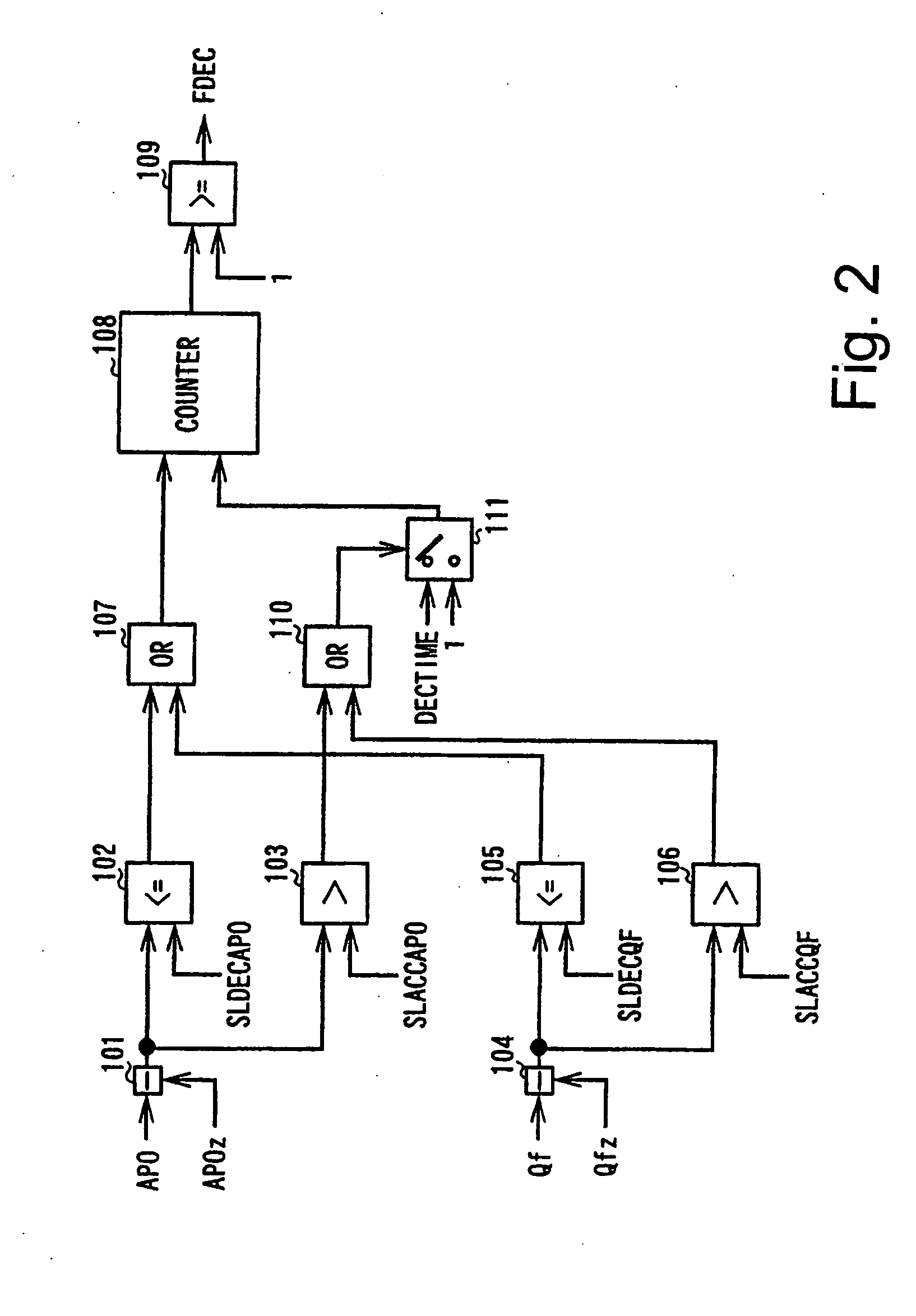
[0072] A subtraction section 501 receives the cylinder intake air flow rate Qcyl and the cylinder intake air flow rate Qcylz of the previous cycle and calculates the difference DQCYL (i.e., DQCYL=Qcyl−Qcylz) between the current cylinder intake air flow rate Qcyl and the cylinder intake air flow rate Qcylz of the previous cycle.

[0073] A comparison section 502 compares the difference DQCYL with a prescribed value SLDQCYL1 and outputs a value of 1 if the differen...

third embodiment

[0079] Referring now to FIG. 11, an operating state detecting section in accordance with a third embodiment will now be explained. In view of the similarity between the prior embodiments and third embodiments, the parts of the third embodiment that are identical to the parts of the prior embodiments will be given the same reference numerals as the parts of the prior embodiments. Moreover, the descriptions of the parts of the third embodiment that are identical to the parts of the prior embodiment may be omitted for the sake of brevity.

[0080] A comparison section 601 compares the absolute value of the difference DQCYL between the cylinder intake air flow rates Qcyl and Qcylz to a prescribed value SLDQCYL2. After the output of the comparison section 502 changes to 1, the comparison section 601 outputs the value 1 when the difference DQCYL reaches the comparatively small prescribed value SLDQCYL2. The prescribed value SLDQCYL2 indicates when the surging has converged and is set to a s...


PUM


Abstract

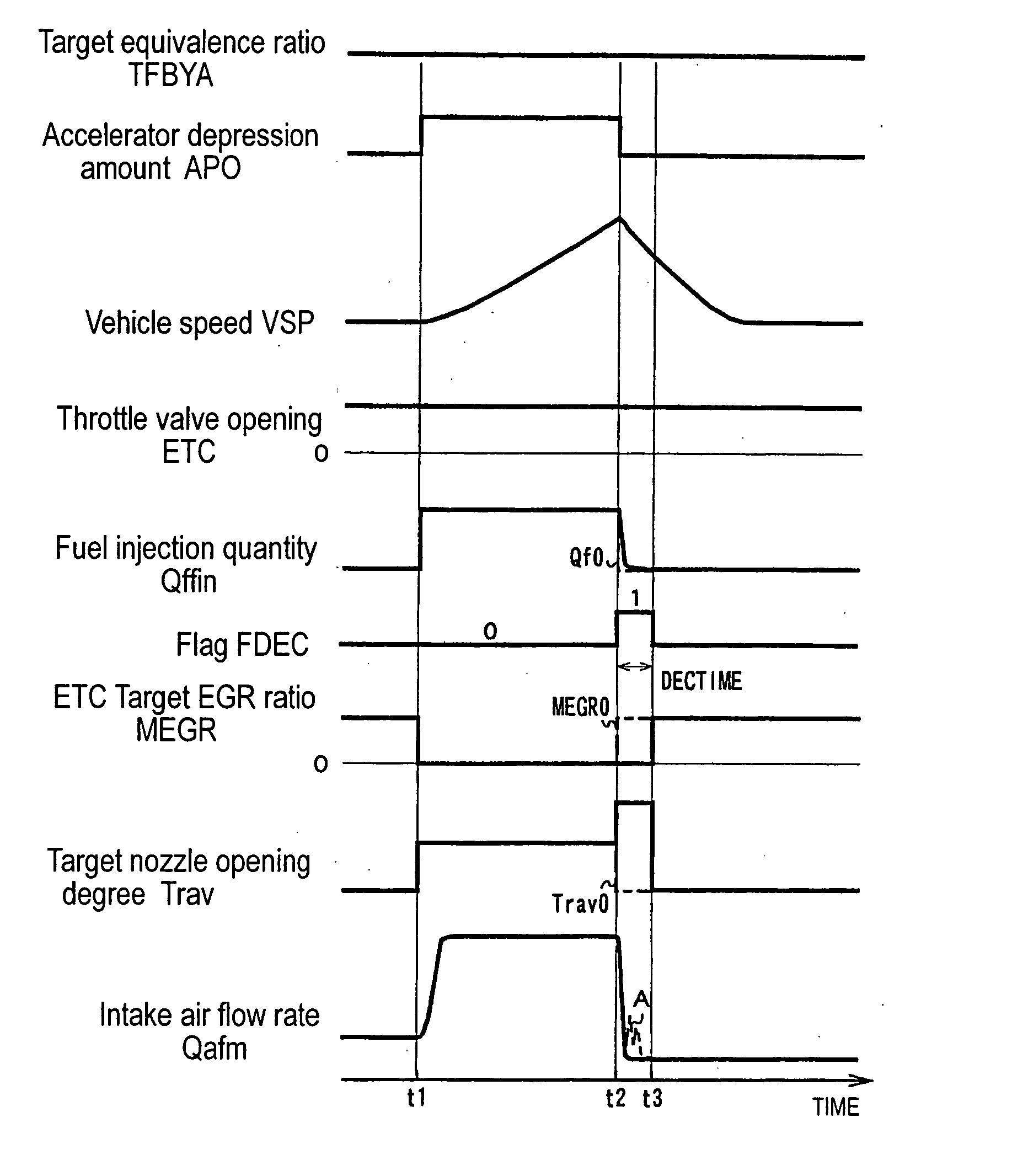
An engine control device is configured to prevent surging in an engine equipped with both a variable-nozzle turbocharger and an EGR device while curbing costs by utilizing existing equipment and avoiding undesirable secondary effects. When the engine is in a prescribed engine operating state in which the fuel injection quantity should be reduced, the EGR quantity delivered by the EGR device is reduced to a value lower than the normal value and the opening degree of the turbine nozzle of the turbocharger is increased. The prescribed engine operating state is defined to exist when the vehicle is decelerating and when the fuel injection quantity is decreased after regeneration of the NOx trapping catalytic converter.

Description

CROSS-REFERENCE TO RELATED APPLICATIONS [0001] This application claims priority to Japanese Patent Application No. 2004-054515. The entire disclosure of Japanese Patent Application No. 2004-054515 is hereby incorporated herein by reference. BACKGROUND OF THE INVENTION [0002] 1. Field of the Invention [0003] The present invention generally relates to a control device for an engine. More specifically, the present invention relates to technology for preventing surging in the turbocharger compressor of an engine equipped with a turbocharger and an EGR device. [0004] 2. Background Information [0005] The idea of supercharging an engine using a turbo-supercharging device (turbocharger) comprising a turbine installed in an exhaust passage and driven by exhaust gas and a compressor installed in an air intake passage and driven by the turbine is well-known. When a turbocharger is used, there is a minimum allowable compressor flow rate that depends on the rotational speed of the turbine or the...

Claims


Application Information

Patent Timeline
IPC IPC(8): F02B37/00F01N3/08F01N3/24F01N3/28F02B37/12F02B37/24F02B39/16F02D9/02F02D11/10F02D21/08F02D23/00F02D41/00F02D41/02F02D41/04F02D41/12F02D41/30F02D43/00F02D45/00F02M25/07
CPCF02B37/00F02D41/0007F02D41/005F02D41/0275F02D41/12Y02T10/47F02D2011/102F02D2200/501F02D2200/602Y02T10/144F02D41/3064Y02T10/12Y02T10/40
Inventor SHIRAKAWA, TAKASHI
Owner NISSAN MOTOR CO LTD
Learn More