Particulate matter concentration measuring apparatus

a technology of concentration measuring apparatus and particle matter, which is applied in the direction of porous material analysis, instruments, suspensions, etc., can solve the problems of difficult to obtain reproducible measurement, difficult to obtain high sensitivity with glass fiber tape, undesirable use of filter tape in continuous measurement, etc., and achieves the effect of easy replacement and convenient mounting

Inactive Publication Date: 2005-09-01
HORIBA LTD
View PDF10 Cites 11 Cited by
  • Summary
  • Abstract
  • Description
  • Claims
  • Application Information

AI Technical Summary

Benefits of technology

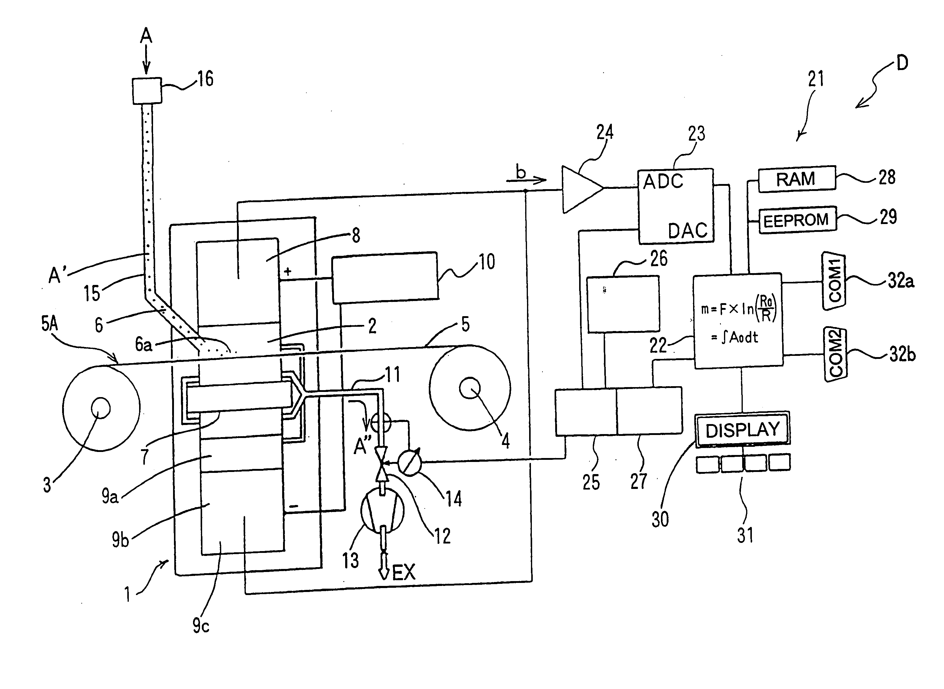
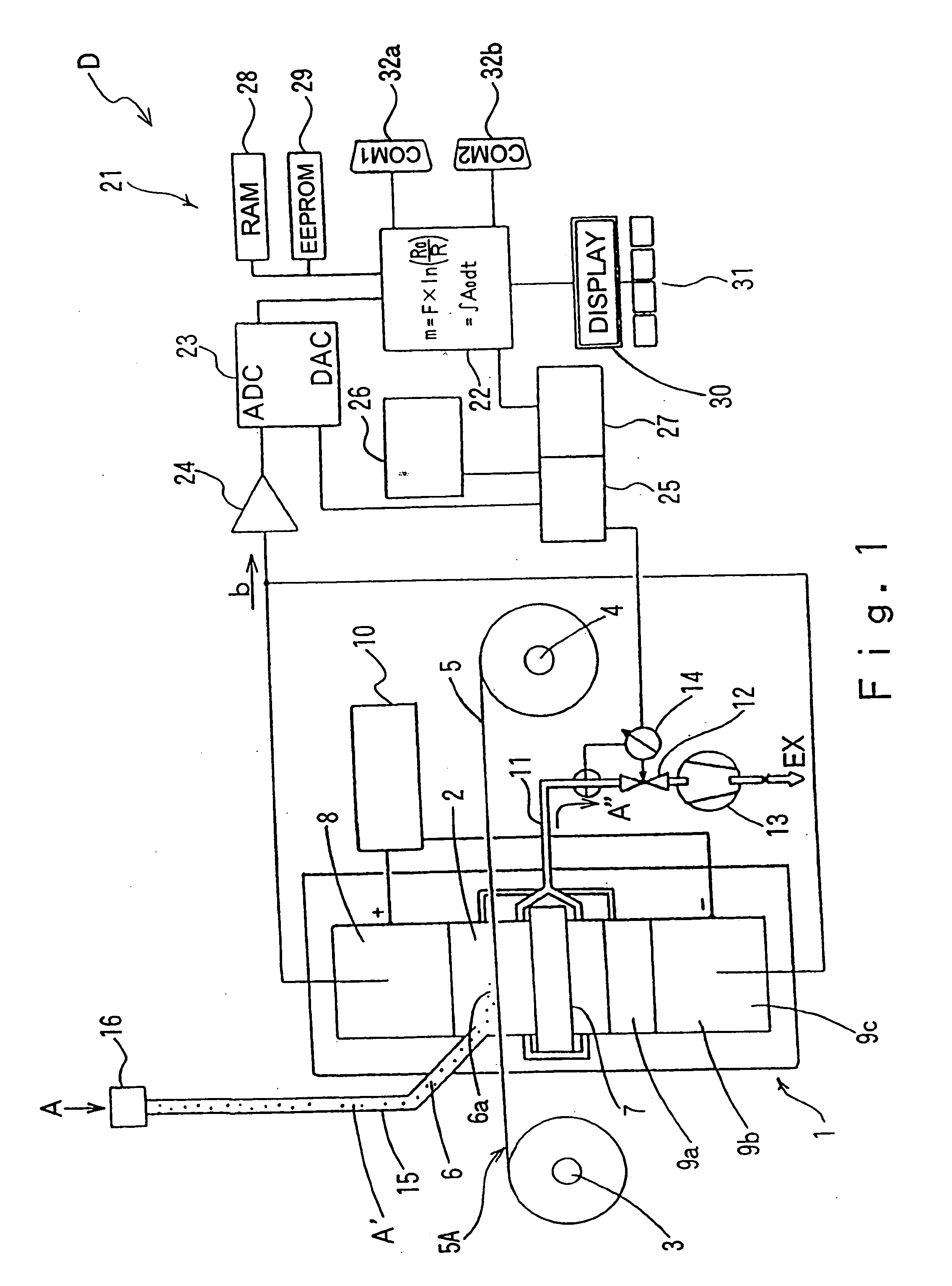
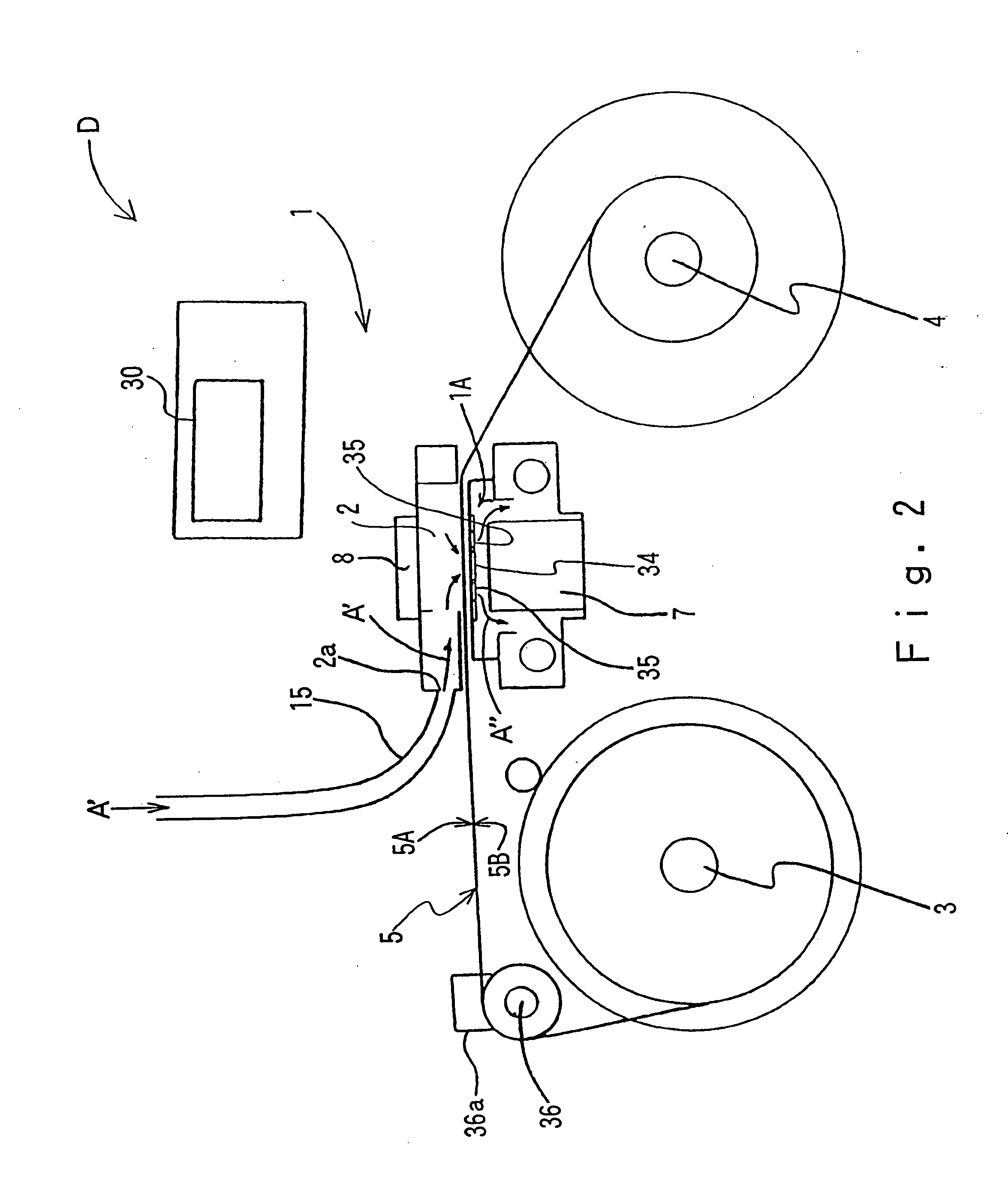
[0034] Further, since the pipe connection portion is formed in a center portion of a cover body, the sample gas introduced via the pipe can be securely introduced just downward, and the sizing device main body 105 can sufficiently achieve a predetermined sizing performance.
[0035] In the case that the PM concentration measuring apparatus has a mounting flange for mounting the sample introduction portion to the sample intake portion of the impact type sampler, the sample introduction portion is a cover body having approximately the same outer shape as an outer shape of the mounting flange, and forming the pipe connection portion in a center portion thereof, and the pipe connection portion is a taper-shaped receiving port, it is possible to mount the cover body to the sample intake portion of the conventional impact type sampler, form the pipe connection portion without substantially changing the shape of the existing impact type sampler, and easily mount the pipe to the taper-shaped receiving port.
[0036] That is, since no great pressure is applied to the pipe connection portion and a flow passage for the sample gas formed by the pipe connected thereto, it is sufficient to maintain an air-tight seal because the sample gas is the atmospheric air, and the current pipe is a flexible hose-like member, it is not necessary to form a screw-type connection portion in order to obtain a strong air-tight seal. It is useful that the connection of the pipe may be easily replaced by making the structure of the pipe connection portion a tapered receiving port.

Problems solved by technology

Accordingly, since the strength of the filter tape 64 cannot be preserved while reducing the weight (the density) of the glass fiber, such filter tape is undesirable for use in continuous measurement.
Further, high sensitivity is difficult to obtain with glass fiber tape since the beta rays are partially absorbed by the glass fiber.
This deformation may result in slight differences in concentration measurements, making it difficult to obtain reproducible measurement results.
Accordingly, in the case of measuring the concentration of the PM collected in accordance with the beta-ray absorption method, any radioactive materials other than the beta-ray source (a sealed ray source) within the measuring apparatus may contribute to an error factor and make it difficult to accurately measure the PM in accordance with the beta-ray absorption detection method.
However, since an error influence by the alpha rays with respect to the beta rays and an error influence by the beta rays existing in the nature generate a great obstacle in the case of measuring the PM2.5 at a high sensitivity, it is desired to make these influences as small as possible.
In any event, it is necessary to perform the mounting which may require a significant cost and time for the purpose of changing the specification of the sizing device, delaying spreading of the sampling of the PM as mentioned in the “Preliminary Manual for Method of Measuring Mass Concentration of Minute Particulate Matter (PM2.5) in Atmospheric Air” above.
Further, it is difficult to carry out a base line test as a basic instruction (confirmation of noise) in a non-dust state corresponding to an important test for confirming a basic performance of the PM concentration measuring apparatus 120.

Method used


Image

  • Particulate matter concentration measuring apparatus
  • Particulate matter concentration measuring apparatus
  • Particulate matter concentration measuring apparatus

Examples


Embodiment Construction

[0057] Reference will now be made in detail to the preferred embodiments of the invention, examples of which are illustrated in the accompanying drawings. While the invention will be described in conjunction with the preferred embodiments, it will be understood that they are not intended to limit the invention to these embodiments. On the contrary, the intention is intended to cover alternatives, modifications and equivalents, which may be included within the spirit and scope of the invention as defined by the appended claims. Furthermore, in the following detailed description of the present invention, numerous specific details are set forth in order to provide a thorough understanding of the present invention. However, it will be obvious to one of ordinary skill in the art that the present invention may be practiced without these specific details. In other instances, well known methods, procedures, components, and circuits have not been described in detail as not to unnecessarily o...


PUM

PropertyMeasurementUnit
timeaaaaaaaaaa
thicknessaaaaaaaaaa
particle diameteraaaaaaaaaa

Abstract

A highly sensitive particulate matter concentration measuring apparatus for measuring a concentration of particulate matter in a sample gas collected in a collecting region formed on a collecting medium, the collecting region being formed by drawing the sample gas through a cross-sectional area of the collecting medium, the collecting medium is a filter tape that includes a porous film made of a fluorine resin and a reinforcing layer provided on the porous film, the particulate matter concentration is measured using a beta-ray absorbing method while removing the error influences of naturally occurring beta radiation, and includes an additional impact type sampler or cyclone type sampler for filtering the sample gas prior to collecting the particulate matter in the collecting region.

Description

CROSS-REFERENCE TO RELATED APPLICATION [0001] This application is based on applications 2002-189201, 2002-237468, 2002-311384, and 2002-319882 filed in Japan, the content of which are hereby incorporated by reference. BACKGROUND OF THE INVENTION [0002] 1. Field of the Invention [0003] The present invention relates to a particulate matter concentration measuring apparatus for measuring a concentration of particulate matter in a sample gas, and specifically to a filter tape used for use in measuring the concentration of the particulate matter. [0004] 2. Description of Related Art [0005] As an apparatus for measuring particulate matter (hereinafter, refer to as PM) in the atmosphere, there is an apparatus which continuously receives fixed flow rate samples of the atmosphere into a sampling tube (a gas introduction pipe) as a sample gas, continuously collects the PM from the sample gas within a vacuum chamber provided in a downstream side of the sampling tube by using a collecting means...

Claims


Application Information

Patent Timeline
Patent Type & Authority Applications(United States)
IPC IPC(8): G01N1/22G01N1/24G01N15/02G01N35/00
CPCG01N1/2205G01N1/24G01N2001/2223G01N35/00009G01N15/0272
Inventor SHINOHARA, MASAYOSLHIMIZUTANI, HIROSHI
Owner HORIBA LTD
Why Eureka
Try Eureka